
Resonant driver with low-voltage secondary side control for high power LED lighting

a technology of led lighting and resonance driver, which is applied in the direction of electric variable regulation, process and machine control, instruments, etc., can solve the problems of emi (electromagnetic interference), additional loss, and distortion of emi, so as to avoid switching losses, minimize emi, and cost-effective

Inactive Publication Date: 2011-07-05
KONINKLIJKE PHILIPS ELECTRONICS NV
View PDF15 Cites 5 Cited by
  • Summary
  • Abstract
  • Description
  • Claims
  • Application Information

AI Technical Summary

Benefits of technology

[0009]The inventive power supply device provides a novel resonant operating galvanic isolating driver topology and control scheme for supplying loads, preferably LEDs. The device can be supplied by a DC voltage, which may be given by the rectified and smoothed mains voltage. The inventive device comprises an inverter, preferably a high-frequency inverter, a transformer, a series capacitor and a secondary rectifier stage. The transformer serves for galvanic isolation and adapts the voltage level, e.g. from 300 volt primary to 30 volt secondary. The resonant circuit is preferably formed by the stray inductance of the transformer and the series capacitor. Thus, the parasitic leakage inductance of the transformer is part of the device. Contrary to known PWM-based converters such as forward and fly back topologies, the leakage inductance does not need to be minimized. This is of advantage for the isolation and winding design and it thus keeps the cost low.
[0035]This measure has the advantage that a simple and hence cost-effective element for measuring the current can be provided.

Problems solved by technology

This causes additional effort since an auxiliary voltage is needed on the secondary side and galvanic isolation has to be foreseen in the feed back path.
If the current measurement is based on a cheap and simple shunt resistor additional losses occur.
Another problem of this known concept can be seen in EMI (electromagnetic interference) distortion typically related to PWM switching topologies.

Method used


Image

  • Resonant driver with low-voltage secondary side control for high power LED lighting
  • Resonant driver with low-voltage secondary side control for high power LED lighting
  • Resonant driver with low-voltage secondary side control for high power LED lighting

Examples


Embodiment Construction

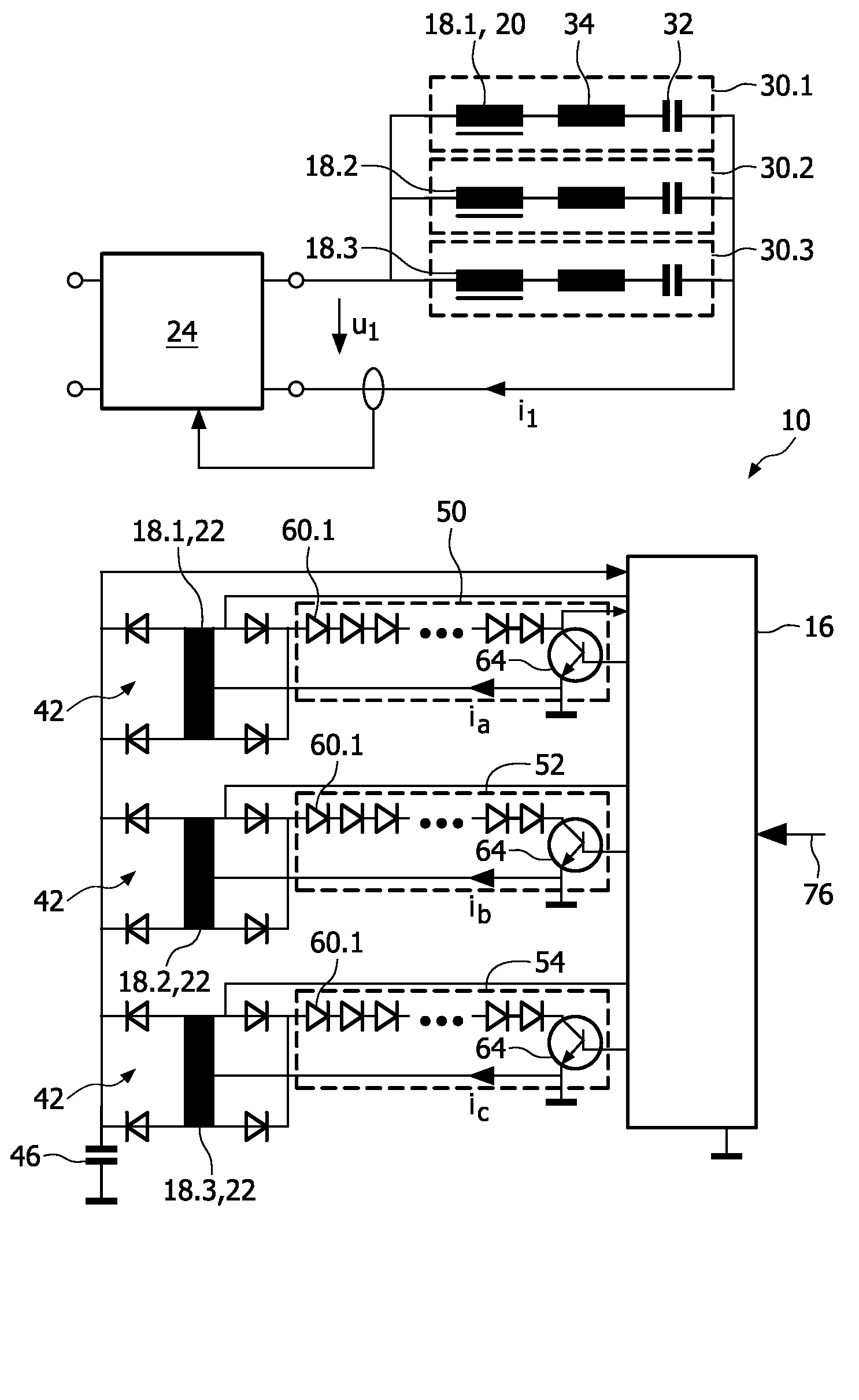
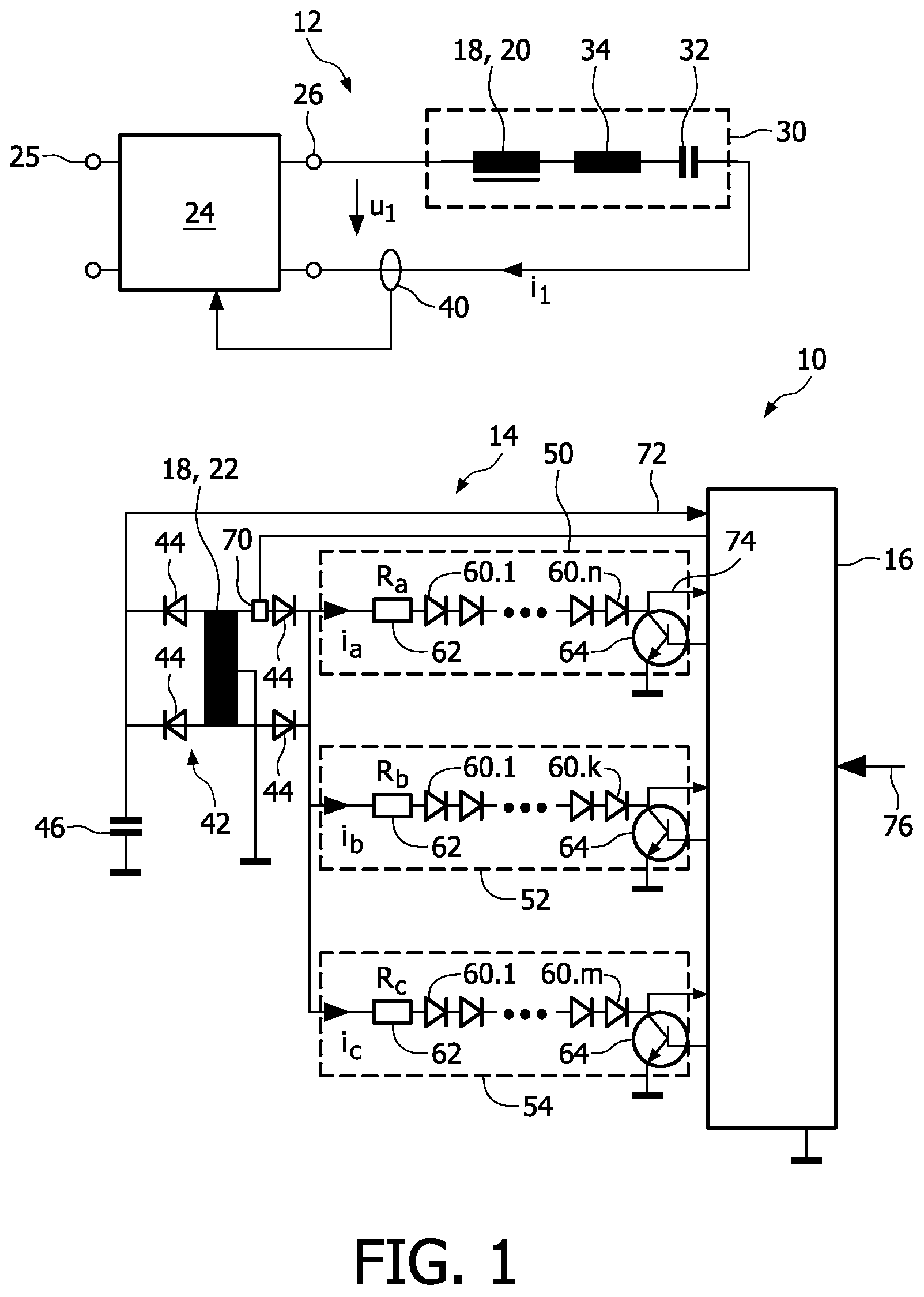
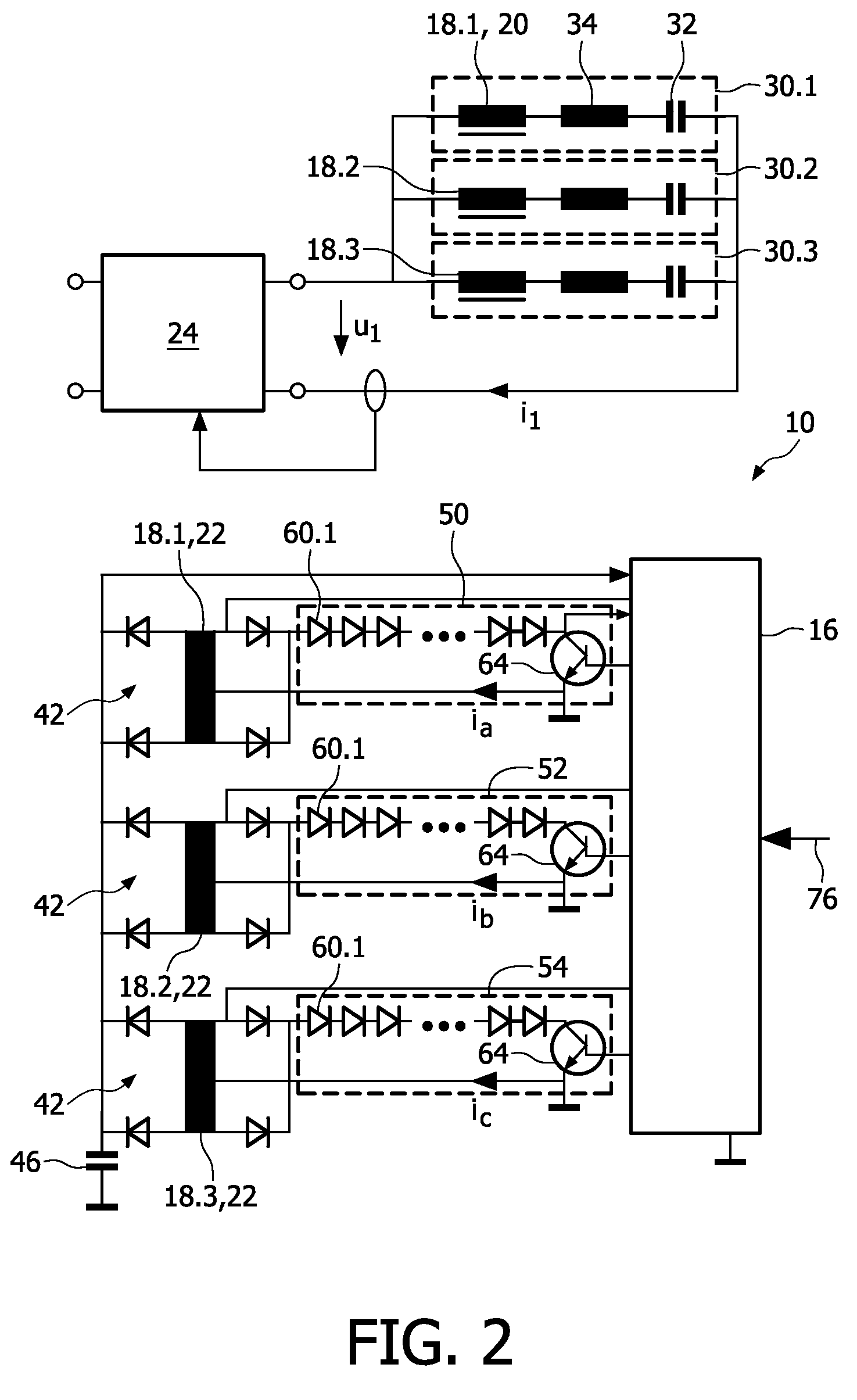
[0043]In FIGS. 1 and 2, two embodiments of a power supply device are shown as block-diagrams. The power supply device is used for supplying a load, preferably a lamp with power, wherein the power is adjustable. The lamp is preferably a light emitting diode (LED) or a plurality of such LEDs, for example connected in series. However, it is to be noted that other electrical loads, preferably other types of lighting systems may also be supplied with the power supply device of the present invention. Here, the term “LED” comprises also organic LEDs (OLED).

[0044]Further, it is to be noted that variations and modifications to the devices shown in FIG. 1 or 2 may be carried out without leaving the scope of the present invention as defined in the appended claims.

[0045]In FIG. 1, the general structure of a power supply device is shown and indicated with reference numeral 10. The power supply device 10 comprises a first circuitry 12 and a second circuitry 14 which are galvanically isolated from...


PUM


Abstract

The present invention relates to a power supply device for supplying power to a load, preferably a LED, comprising a first circuitry (12) with an inverter unit (24) adapted to provide an AC voltage, preferably a rectangular voltage, and a resonant circuit (30) with a capacitance (32) and an inductance (34), a second circuitry (14) with a rectifier unit (42), a switch (64) and said load (60), said switch being adapted to switch said load on and off, a controller unit (16) adapted to control said switch (64) as to adjust the power provided to said load (60) without any measurement signal from said primary circuitry (12), and a transformer (18) with a primary side (20) and a secondary side (22), said primary side being connected to said first circuitry (12) and said secondary side (22) being connected to said second circuitry (14), preferably said rectifier, so that said first and second circuitries are galvanically isolated.

Description

[0001]This application is a national stage application under 35 U.S.C. §371 of International Application No. PCT / IB2007 / 053474 filed on Aug. 29, 2007, and published in the English language on Mar. 13, 2008 as International Publication No. WO / 2008 / 029325, which claims priority to European Application No. 06120243.8, filed on Sep. 7, 2006, incorporated herein by reference.FIELD OF THE INVENTION[0002]The present invention relates to a power supply device for supplying power to a load, preferably a light emitting diode (LED).BACKGROUND OF THE INVENTION[0003]Generally, solid-state lighting is of growing interest for residential, automotive and professional applications. Since solid-state lamps, such as LEDs, cannot be supplied from a battery or the AC mains directly, electronic power drivers (also called power supply devices) are needed for power effective driving. For efficiency reasons, LED drivers have to be operated in a switched mode. The drivers convert the available DC or AC volta...

Claims


Application Information

Patent Timeline
Patent Type & Authority Patents(United States)
IPC IPC(8): G05F1/00H05B44/00
CPCH02M3/33561H02M3/337H05B33/0818H05B33/0851Y02B20/346Y02B70/1433H05B45/10Y02B20/30Y02B70/10H05B45/382H05B45/39H02M3/33573H02M3/33571H02M3/01
Inventor LOEF, CHRISTOPHWENDT, MATTHIAS
Owner KONINKLIJKE PHILIPS ELECTRONICS NV
Learn More