Door closer

a door and closer technology, applied in the field of door closers, can solve the problem of inability to convert to fire protection functions, and achieve the effect of inexpensive adaptation

Active Publication Date: 2014-05-27
DORMAKABA DEUT GMBH
View PDF30 Cites 11 Cited by
  • Summary
  • Abstract
  • Description
  • Claims
  • Application Information

AI Technical Summary

Benefits of technology

[0016]It is an object of the invention to provide a door closer that can be manufactured inexpensively adapted to the respective...

Problems solved by technology

Thus, a conversion to a fire protection function would be impossib...

Method used


Image

  • Door closer
  • Door closer
  • Door closer

Examples


first embodiment

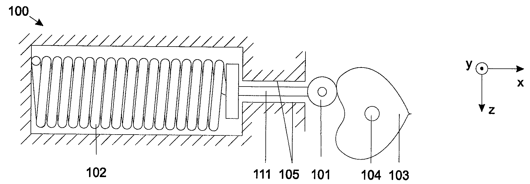
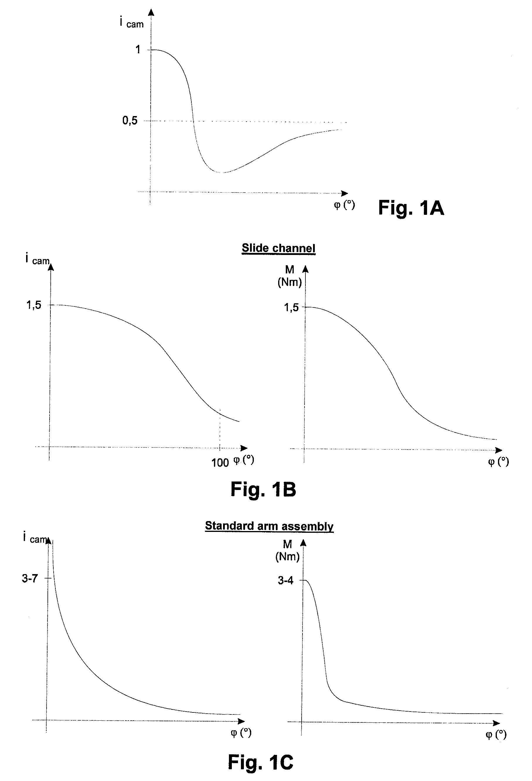
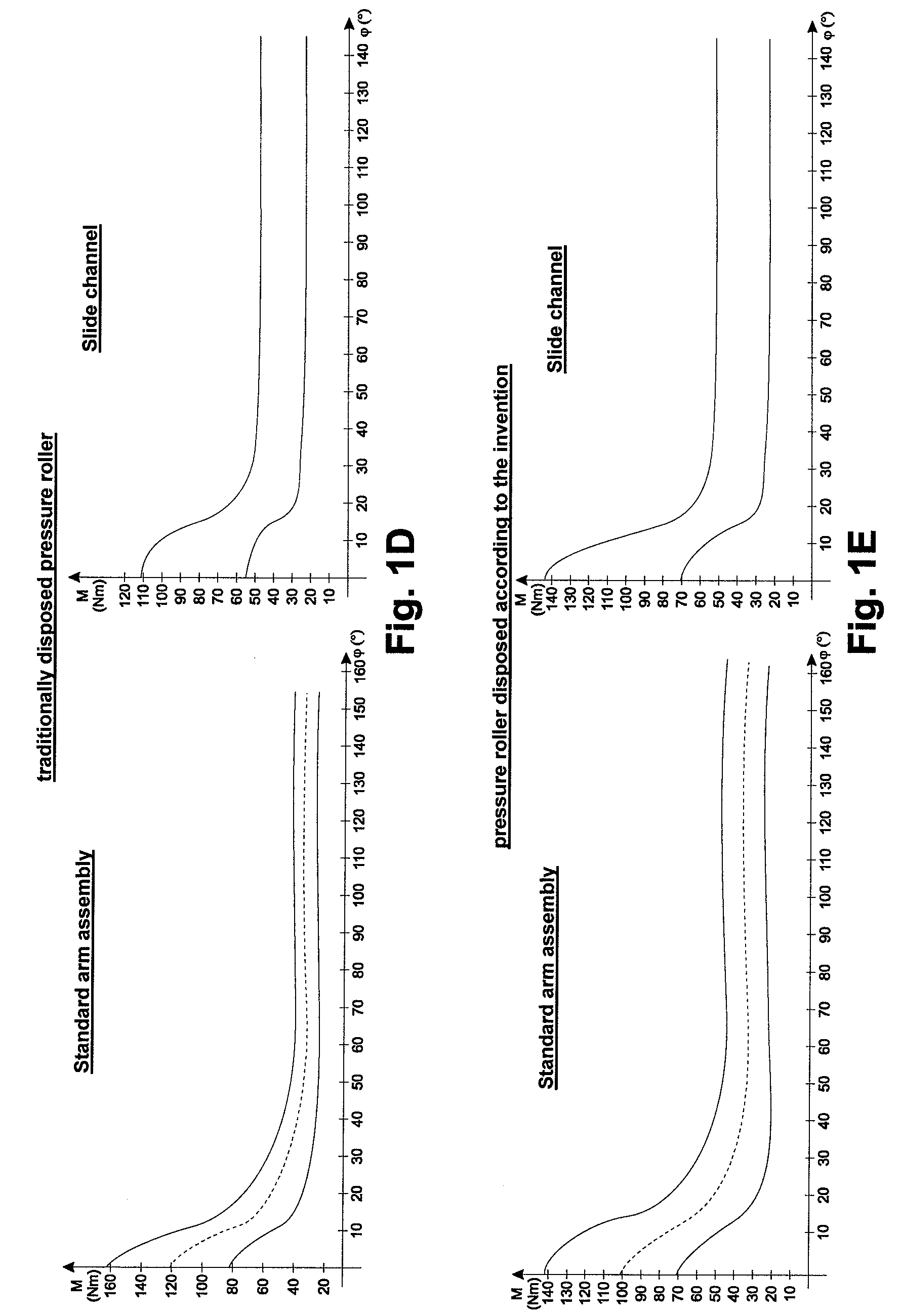
[0063]A door closer 100 according to the invention, as shown in the FIGS. 2A to 2C, has a pressure roller 101, which is pressed against a cam disc 103 by means of a closer spring 102, which disc is torsion-resistantly disposed on an output shaft 104 of the closer portion 100.

[0064]The pressure roller 101 is disposed such that a line, which is substantially defined by the translational movement thereof, bypasses the axial center of the output shaft 104.

[0065]As shown in FIG. 2A, the closer spring 102 is disposed on a side of the cam disc 103, on which the pressure roller 101 is likewise disposed. The closer spring 102 presses the pressure roller 101 against the cam disc 103 by means of an operational connection in the shape of a connecting rod 111. The connecting rod 111 is guided in a guide 105 such that it is only movable translationally towards the cam disc 103 or away from it. A force of the closer spring 102 thus acts in the +x-coordinate direction.

[0066]As an alternative, as sh...

second embodiment

[0068]In a door closer 100 according to the invention shown in FIG. 3A, the closer spring 102 is in operational connection with a pressure roller 101 by means of a transmission gear, which preferably has the shape of a lever assembly. Via a lever 107, the closer spring 102 pulls the pressure roller 101 into the direction of the cam disc 103, thus acting in the −x-coordinate direction. Even if the path of motion of the pressure roller 101 describes a circle, it will bypass the axial center of the output shaft 104 along the entire path of motion.

[0069]FIG. 3B illustrates an alternative lever assembly. In contrast to FIG. 3A, in this case, the closer spring 102 presses the pressure roller 101 against the cam disc 103 by means of a lever 107, this means in the +x-coordinate direction. With regard to the pressure roller 101, the same findings apply for FIG. 3A.

third embodiment

[0070]In a door closer 100 according to the invention shown in FIG. 4, it is intended to dispose the assembly of closer spring 102 and the operational connection thereof with the pressure roller 101 (for example the lever 107) rotating about a point, this means at an angle α, which point does not correspond to the axial center of an output shaft 104 of the door closer 100.


PUM


Abstract

A door closer is described, which has an output shaft, on which a cam disc is torsion-resistantly disposed, and has a pressure roller. By means of an operational connection, a closer spring presses the pressure roller against a running surface of the cam disc. In relation to an axial center of the output shaft, the pressure roller is disposed such that, during opening or closing of a swing leaf coupled to the output shaft, the pressure roller is movable along a path. Due to the fact that the path bypasses the axial center of the output shaft and on account of the configuration of the running surface of the cam disc, at a respective opening angle of the swing leaf, in different modes of operation of the door closer, a very similar or identical torque is respectively applied to the output shaft.

Description

CROSS REFERENCE TO RELATED APPLICATIONS[0001]This is a U.S. national stage of International Application No. PCT / EP2007 / 010774, filed on Dec. 11, 2007, claiming priority to German Application No. 10 2007 002 651.1, filed on Jan. 12, 2007, the entire contents of both applications being expressly incorporated herein by reference.BACKGROUND OF THE INVENTION[0002]1. Field of the Invention[0003]The invention relates to a door closer based on a cam mechanism.[0004]2. Description of the Related Art[0005]Typically, door closers with a cam mechanism have a cam disc, which is torsion-resistantly disposed on an output shaft and has a running surface, on which a pressure roller rolls which is pressed against said surface by means of a closer spring.[0006]The shape of the running surface determines the characteristics of the torque applied to the operated swing leaf during a closing movement, which is the torque curve resulting therefrom.[0007]When seen in a longitudinal extension of the output s...

Claims


Application Information

Patent Timeline
IPC IPC(8): E05F3/10E05D11/10
CPCE05Y2900/132E05Y2600/40E05Y2201/638E05Y2800/17E05F3/104E05Y2201/688E05Y2201/604
Inventor BUSCH, SVEN
Owner DORMAKABA DEUT GMBH
Why Eureka
Try Eureka