
Pump

a technology for pumping and fluid, applied in the direction of machines/engines, oscillating piston liquid engines, positive displacement liquid engines, etc., can solve the problems of reduced use of the actuator on the fluid, reduced pump efficiency, and reduced pump efficiency, and achieves reduced vibration mode matching of the substantial area fraction of the end walls and working fluid volume, and limited piezoelectric material volume. , the effect of increasing the outer diameter

Active Publication Date: 2014-05-27
TTP VENTUS LTD
View PDF6 Cites 16 Cited by
  • Summary
  • Abstract
  • Description
  • Claims
  • Application Information

AI Technical Summary

Benefits of technology

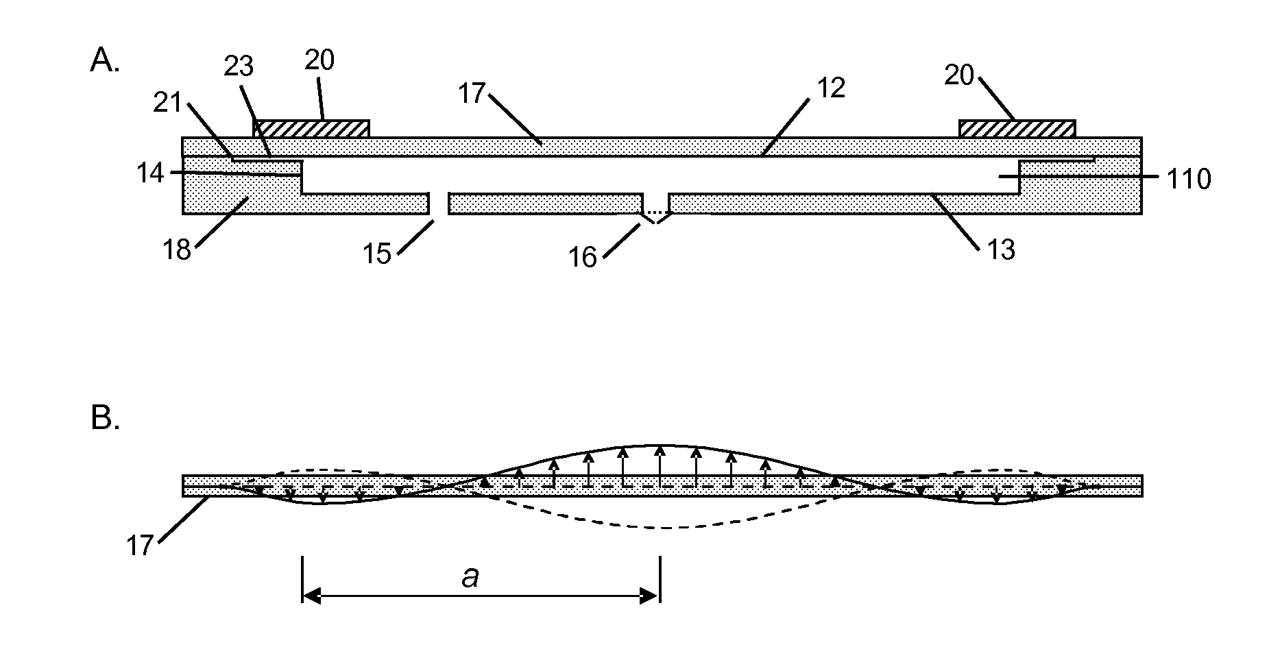
The design achieves improved mode-matching and increased efficiency by positioning the actuator vibration antinode at the cavity edge, reducing strain on the piezoelectric material, and allowing for a larger volume of piezoelectric material, thereby enhancing the pump's power output and extending its lifespan.

Problems solved by technology

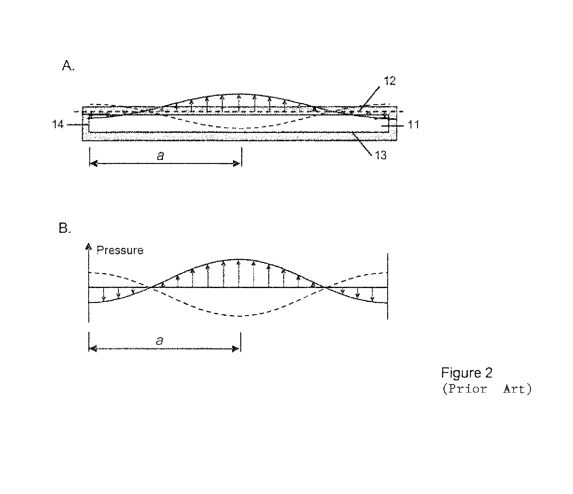
In a pump which is not mode-matched there may be areas of the end-wall surface in which the work being done by the end-wall on the fluid reduces rather than enhances the amplitude of the pressure oscillation in the fluid within the cavity: the useful work done by the actuator on the fluid is reduced and the pump becomes less efficient.
Indeed, the failure of mode-matching occurs principally at the outer radii of the end-walls, so a substantial area fraction of the end walls and working fluid volume are not vibrationally mode-matched.
However, it is not obvious how such a pump may be constructed, as the actuator must have an antinode of vibration at the side-wall, to which it might normally be mounted.
There are two limitations to this design.
As there is a limit to the power that may be delivered efficiently per unit volume of piezoelectric material, this limitation on piezoelectric disc volume puts a limit on the useful power output of the actuator.
Secondly the piezoelectric disc is subject to high strain at its centre, where the amplitude of motion of the actuator and its radius of curvature are highest.
It is known that high strains can lead to the degradation of piezoelectric material through its depolarisation, thereby reducing the amplitude of motion of the actuator and thus limiting actuator lifetime.
Such high strain at the centre of the actuator may also lead to fatigue of the glue layer between the piezoelectric disc and the second disc if the two are joined by gluing, again leading to reduced actuator lifetime.

Method used


Image

  • Pump
  • Pump
  • Pump

Examples


Embodiment Construction

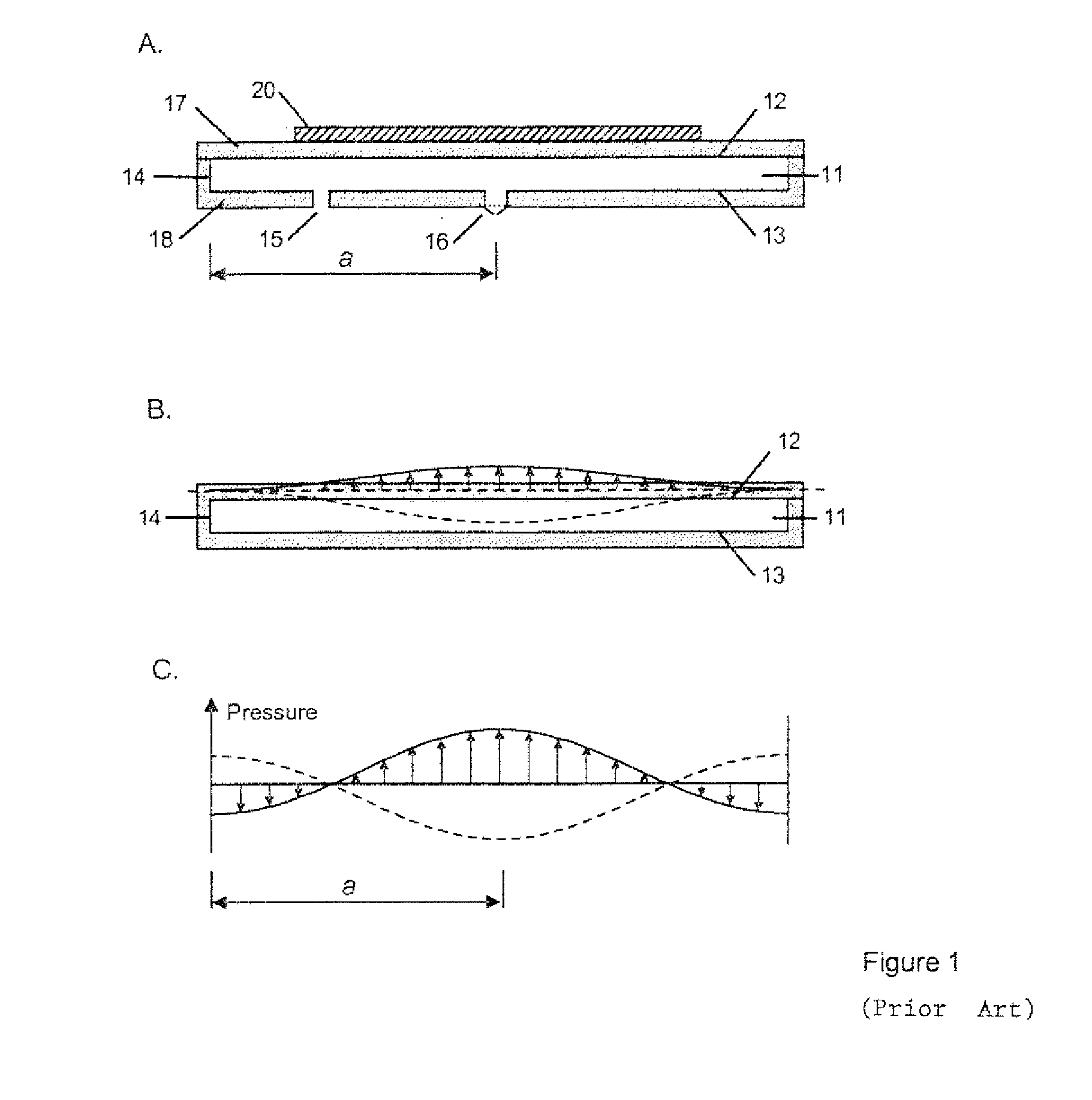
[0054]FIG. 1A is a schematic representation of the pump according to the prior art. A cavity 11 is defined by end walls 12 and 13, and a side wall 14. The cavity is substantially circular in shape, although elliptical and other shapes could be used. The cavity 11 is provided with a nodal air inlet 15, which in this example is unvalved. There is also a valved air outlet 16 located substantially at the centre of end wall 13. The first end-wall 12 is defined by the lower surface of a disc 17 attached to a main body 18. The inlet and outlet pass through the main body 18.

[0055]The actuator comprises a piezoelectric disc 20 attached to a disc 17. When an appropriate electrical drive is applied, the actuator is caused to vibrate in a direction substantially perpendicular to the plane of the cavity, thereby generating radial pressure oscillations within the fluid in the cavity.

[0056]FIG. 1B shows one possible displacement profile of the driven wall 12 of the cavity. In this case the amplitu...


PUM


Abstract

A fluid pump comprising a chamber which, in use, contains a fluid to be pumped, the chamber including a main cavity having a substantially cylindrical shape bounded by first and second end walls and a side wall and a secondary cavity extending radially outwards of the main cavity, one or more actuators which, in use, cause oscillatory motion of the first end wall in a direction substantially perpendicular to the plane of the first end wall, and whereby, in use, the axial oscillations of the end walls drive radial oscillations of the fluid pressure in the main cavity, and wherein the secondary cavity spaces the side wall from the first end wall such that the first end wall can move relative to the side wall when the actuator is activated.

Description

FIELD OF THE INVENTION[0001]This invention relates to a pump for fluid and, in particular to a pump in which the pumping cavity is closely a disc-shaped cylindrical cavity, having closely-circular end walls. The design of such a pump is disclosed in WO2006 / 111775.BACKGROUND OF THE INVENTION[0002]In such a pump one or both end walls are driven into oscillating displacement in a direction substantially perpendicular to the plane of the end wall by an actuator. Where an end wall is so driven, that end-wall surface may, but need not, be itself formed as an element of a composite vibration actuator such as a piezoelectric unimorph or bimorph. Alternatively, the end wall may be formed as a passive material layer driven into oscillation by a separate actuator in force-transmitting relation (e.g. mechanical contact, magnetic or electrostatic) with it.[0003]It is preferable to match the spatial profile of the motion of the driven end wall(s) to the spatial profile of the pressure oscillation...

Claims


Application Information

Patent Timeline
Patent Type & Authority Patents(United States)
IPC IPC(8): F04B17/03
CPCF04B45/047F04F7/00F04B43/046F04B45/10
Inventor MCCRONE, JAMES EDWARDBUCKLAND, JUSTIN RORKEBLAKEY, DAVID MARK
Owner TTP VENTUS LTD
Learn More