Unlock instant, AI-driven research and patent intelligence for your innovation.

Touch input device and touch sensor circuit

a technology of touch input device and touch sensor, which is applied in the direction of instruments, computing, electric digital data processing, etc., can solve the problems of high cost, large area, and serious distortion of touch input device, and achieve the effect of not being ideal for a modern application, and reducing the cost of the touch input devi

Inactive Publication Date: 2014-05-27
RAYDIUM SEMICON
View PDF15 Cites 0 Cited by
  • Summary
  • Abstract
  • Description
  • Claims
  • Application Information

AI Technical Summary

Benefits of technology

This approach reduces implementation costs and circuit area, enabling compact and low-power touch detection in modern electronic devices while maintaining high precision.

Problems solved by technology

For example, based on the touch panel or touch pad nowadays, user may simply operate the device or type some sentences with their finger or a touch pen, instead of using the mouse or keyboard to type in the traditional and inconvenient way.
Serious distortion will happen if all capacitive nodes are compared to one identical reference value.
However, to dispose a capacitor over 10 pF in an integrated circuit may bring high cost and occupy large area.
To implement a huge reference capacitor array 124 into the touch input device 1 is not an ideal solution for a modern application.

Method used


Image

  • Touch input device and touch sensor circuit
  • Touch input device and touch sensor circuit
  • Touch input device and touch sensor circuit

Examples


Embodiment Construction

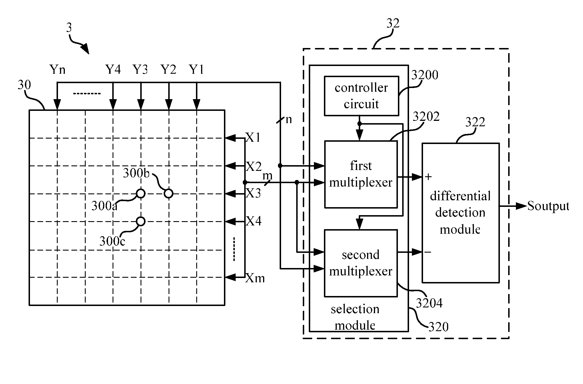
[0025]Please refer to FIG. 3. FIG. 3 is a schematic diagram illustrating a touch input device 3 according to a first embodiment of the invention. The touch input device 3 includes a touch panel 30 and a corresponding touch sensor circuit 32. In this embodiment, the touch sensor circuit 32 can be produced independently and be widely applied in various electronic systems with touch input function. In other words, the touch sensor circuit 32 is not limited to be implemented in the touch input device 3 of the embodiment.

[0026]In this embodiment, the touch panel 30 includes a plurality of X-directional conductive lines (X1˜Xm) and a plurality of Y-directional conductive lines (Y1˜Yn). The X-directional conductive lines and the Y-directional conductive lines are arranged in a grid shape. As shown in FIG. 3, the X-directional conductive lines are disposed in parallel direction, and the Y-directional conductive lines are disposed in vertical direction, such that to form an intersectional gr...


PUM


Abstract

The invention discloses a touch input device and a touch sensor circuit. The touch input device includes a touch panel, a selection module and a differential detection module. The touch panel includes a plurality of capacitive nodes thereon. The selection module is electrically connected with the capacitive nodes of the touch panel. The selection module selects a first capacitive node and a second capacitive node from the capacitive nodes. The second capacitive node is close to the first capacitive node. The differential detection module, electrically connected to the selection module, is used for detecting a capacitance difference between the first capacitive node and the second capacitive node. According to the capacitance difference, the differential detection module generates a touch detection signal.

Description

BACKGROUND OF THE INVENTION[0001]1. Field of the Invention[0002]The invention relates to a touch input device and a touch sensor circuit, and more particularly to a touch input device and a touch sensor circuit with differential detection.[0003]2. Description of the Prior Art[0004]With the development of information technology, the electronic products become more diversified and humanized. For example, based on the touch panel or touch pad nowadays, user may simply operate the device or type some sentences with their finger or a touch pen, instead of using the mouse or keyboard to type in the traditional and inconvenient way.[0005]There are a number of types of touch panel technology: resistive type, capacitive type, optical type and surface acoustic wave type. The resistive-typed touch panel mainly includes upper and lower ITO glass layers. When an object touches the upper ITO glass layer and presses it toward the lower ITO glass layer, the controller of the touch panel will genera...

Claims


Application Information

Patent Timeline
Patent Type & Authority Patents(United States)
IPC IPC(8): G06F3/045
CPCG06F3/044G06F3/0416G06F3/04164G06F3/04166G06F3/0446
Inventor CHOU, SHIH-TZUNGKUANG, YUWU, ZONG-LINRAO, YONG-NIEN
Owner RAYDIUM SEMICON