Optical connector and method for assembling same

a technology of optical connectors and connectors, which is applied in the field of optical connectors, can solve the problems of warping of the reinforcement sleeves, increasing the size of the optical connector, and difficulty in high-density arrangement of a plurality of such optical connectors having an optical fiber cord, and achieves the effect of high density arrangemen

Active Publication Date: 2014-06-03
SEI OPTIFRONTIER CO LTD +1
View PDF7 Cites 31 Cited by
  • Summary
  • Abstract
  • Description
  • Claims
  • Application Information

AI Technical Summary

Benefits of technology

[0013]According to the present invention, it is possible to fix, without enlarging the size of an optical connector, the sheath of an optical fiber cord to the optical connector. This enables high density arrangement of a plurality of optical connectors having an optical fiber cord.

Problems solved by technology

If any structure for fixing the sheath of the optical fiber cord is provided, it would increase the size of the optical connector, and consequently high-density arrangement of a plurality of such optical connectors having an optical fiber cord would become difficult.
Providing one rod-shaped reinforcement only might cause warping of the reinforcement sleeve when the reinforcement sleeve is subjected to heat shrink.
However, providing a plurality of rod-shaped reinforcements in the reinforcement sleeve would increase the size of a reinforcement sleeve.
Since such a spacer is a minute part, it is difficult to perform positioning of the ferrule body and the spacer, which would result in degradation of workability in the assembling of the optical connector.

Method used


Image

  • Optical connector and method for assembling same
  • Optical connector and method for assembling same
  • Optical connector and method for assembling same

Examples


Embodiment Construction

[0024]Hereinafter, preferred embodiments of the present invention will be described in detail with reference to the accompanying drawings. In the drawings, an identical mark represents the same element and the repetition of explanation is omitted. The dimensional ratios in the drawings are not always exact.

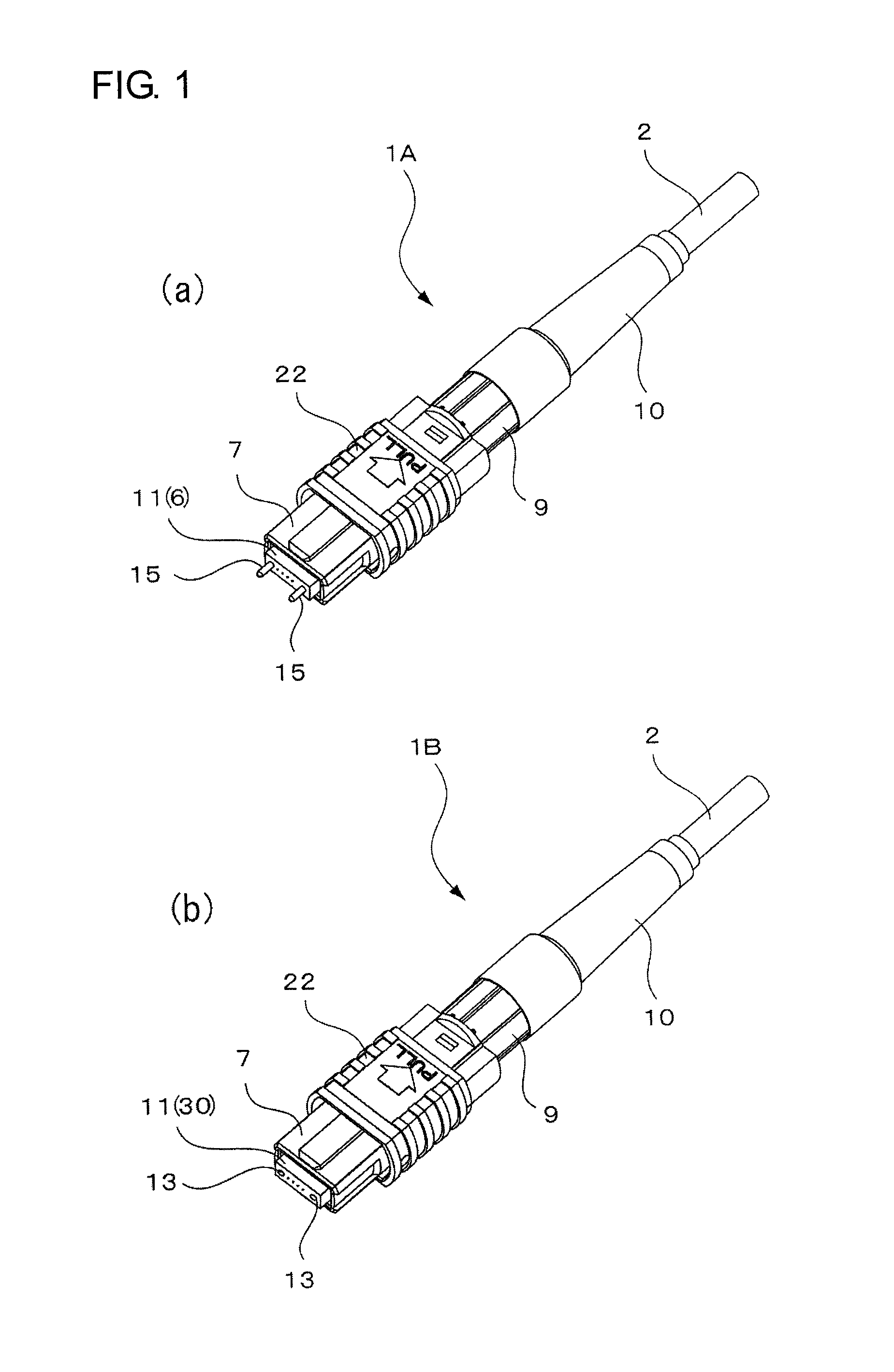
[0025]Region (a) of FIG. 1 is a perspective view showing a state in which an optical fiber cord 2 is attached to a male-type MPO connector 1A which is an embodiment of the present invention (an optical connector having an optical cord), and Region (b) is a perspective view similarly showing a state in which an optical fiber cord 2 is attached to a female-type MPO connector 1B. The optical connectors 1A and the 1B are detachably coupled together through an optical adapter (not shown).

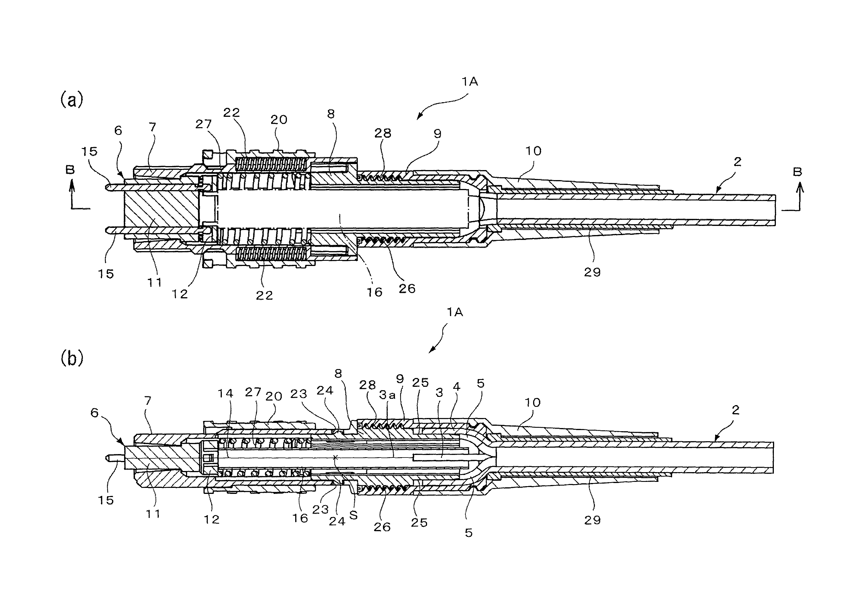
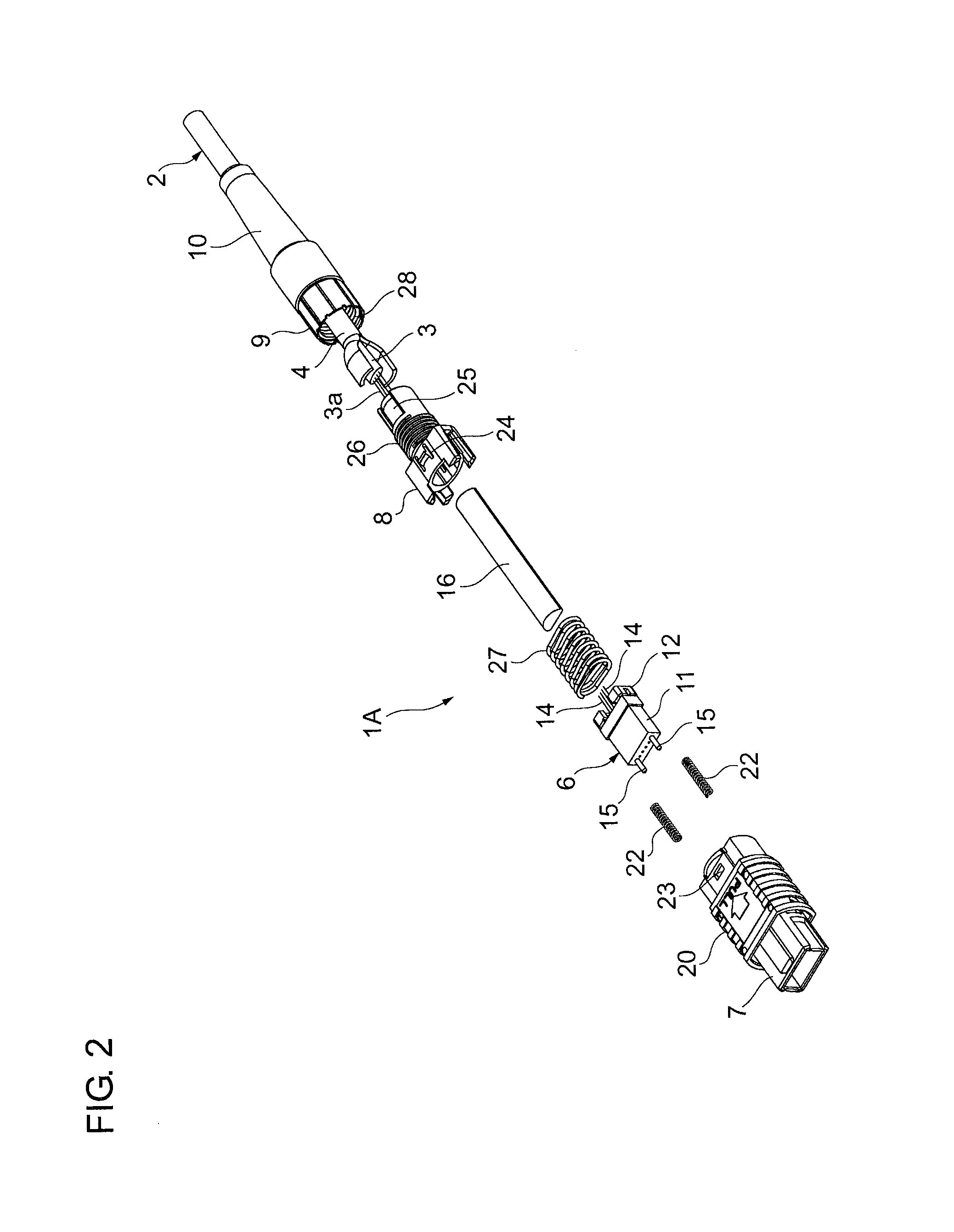
[0026]FIG. 2 is an exploded perspective view of a male-type MPO connector 1A. In FIG. 3, Regions (a) and (b) show sectional views of the male-type MPO connector 1A, whereas Region (b) is a sectional vi...


PUM

PropertyMeasurementUnit
widthaaaaaaaaaa
thicknessaaaaaaaaaa
thicknessaaaaaaaaaa

Abstract

An optical connector to which an optical fiber cord including an optical fiber ribbon and a sheath is to be attached includes: a ferrule member a fusion splice protection sleeve, housing and a fixing member. The ferrule member holds a plurality of embedded fibers which are to be fusion-spliced respectively to a plurality of optical fibers constituting the optical fiber ribbon. The fusion splice protection sleeve protects a fusion-spliced portion. The housing houses the ferrule member and the fusion splice protection sleeve. The housing has, at the rear end, a recess for receiving a bifurcated portion of the sheath. The fixing member fixes the sheath to the housings and by holding it.

Description

CROSS-REFERENCE TO RELATED APPLICATIONS[0001]This U.S. National stage application claims priority under 35 U.S.C. §119(a) to Japanese Patent Application No. 2011-005999, filed in Japan on Jan. 14, 2011, the entire contents of which are hereby incorporated herein by reference.BACKGROUND OF THE INVENTION[0002]1. Field of the Invention[0003]The present invention relates to an optical connector to which an optical fiber cord including an optical fiber ribbon is to be attached, and also to a method of attaching an optical fiber cord to the optical connector.[0004]2. Description of the Background Art[0005]Japanese Patent Application Publication No. 2010-224195 describes an optical connector to which an optical fiber cord is attached such that a splice reinforcement part and a ferrule are provided in a housing of the optical connector altogether, wherein the splice reinforcement part is a part reinforced with a reinforcing sleeve at a fusion spliced portion of embedded optical fibers, whic...

Claims


Application Information

Patent Timeline
Patent Type & Authority Patents(United States)
IPC IPC(8): G02B6/255
CPCG02B6/2558G02B6/3885G02B6/255G02B6/3846G02B6/3887G02B6/38875Y10T29/49826
Inventor SHITAMA, SEIJITAMEKUNI, YOSHIKYOYOKOMACHI, YUKIHIROUKITA, YOSHIOKIMURA, MOTOYOSHI
Owner SEI OPTIFRONTIER CO LTD
Why Eureka
Try Eureka