Liquid applicator

a liquid applicator and liquid technology, applied in the field of liquid applicators, can solve the problems of inability to replace liquid in the tank, inability to replenish liquid, and inability to replace liquid easily, so as to reduce the volume capacity of the tank

Active Publication Date: 2014-06-03
KOTOBUKI & CO LTD
View PDF22 Cites 5 Cited by
  • Summary
  • Abstract
  • Description
  • Claims
  • Application Information

AI Technical Summary

Benefits of technology

[0007]The present invention is accomplished in view of the above defects and the object thereof is to provide a liquid applicator allowing a liquid to be easily replenished and replaced, as well as capable of containing a large amount of liquid.
[0009]According to an aspect of the present invention, the volume capacity of the tank can be varied by pushing or pulling the sliding cylinder to slide the sliding cylinder with respect to the main body. Accordingly, it is possible to expand the volume capacity of the tank so as to make negative pressure in the tank, which causes a liquid to be sucked into the tank and thus the liquid is introduced into the tank. In this manner, a liquid can be replenished into the tank. On the other hand, it is possible to reduce the volume capacity of the tank so as to make positive pressure in the tank, which causes a liquid in the tank to be discharged. Therefore, liquid replacement is also easily performed with combination of discharging and introducing.
[0010]In addition, the whole length of the liquid applicator can be decreased to improve its portability by sliding the sliding cylinder to reduce the volume capacity of the tank while not in use. While in use, the volume capacity of the tank can be increased by sliding the sliding cylinder so as to contain a large amount of liquid. Further, since the whole length of the liquid applicator can be increased, the liquid applicator is easy to grip by hand so as to improve its handleability.
[0013]According to an aspect of the present invention, the main body is provided with a flexible portion, at least a part of which adjoins the tank, for allowing the volume capacity of the tank to be varied by pushing the flexible portion.
[0014]In order to apply a liquid from the tip end applicator body while in use of the liquid applicator, the flexible portion is pushed to reduce the volume capacity of the tank and thus a liquid can be supplied into the tip end applicator body.

Problems solved by technology

In such conventional liquid applicator, a liquid in the tank cannot be replenished or replaced with another liquid.
Therefore, it is not possible to change a type of the liquid in the tank and once the liquid runs out, there is no option but to throw away, that is, the container is of throwaway type.
However, unfortunately, with the applicator described in the above patent application, the liquid can be replenished but cannot be replaced easily, and further, the portable applicator has to be longer in order to hold a larger amount of liquid.

Method used


Image

  • Liquid applicator
  • Liquid applicator
  • Liquid applicator

Examples


Embodiment Construction

[0024]The present invention will be described hereinafter with reference to the drawings.

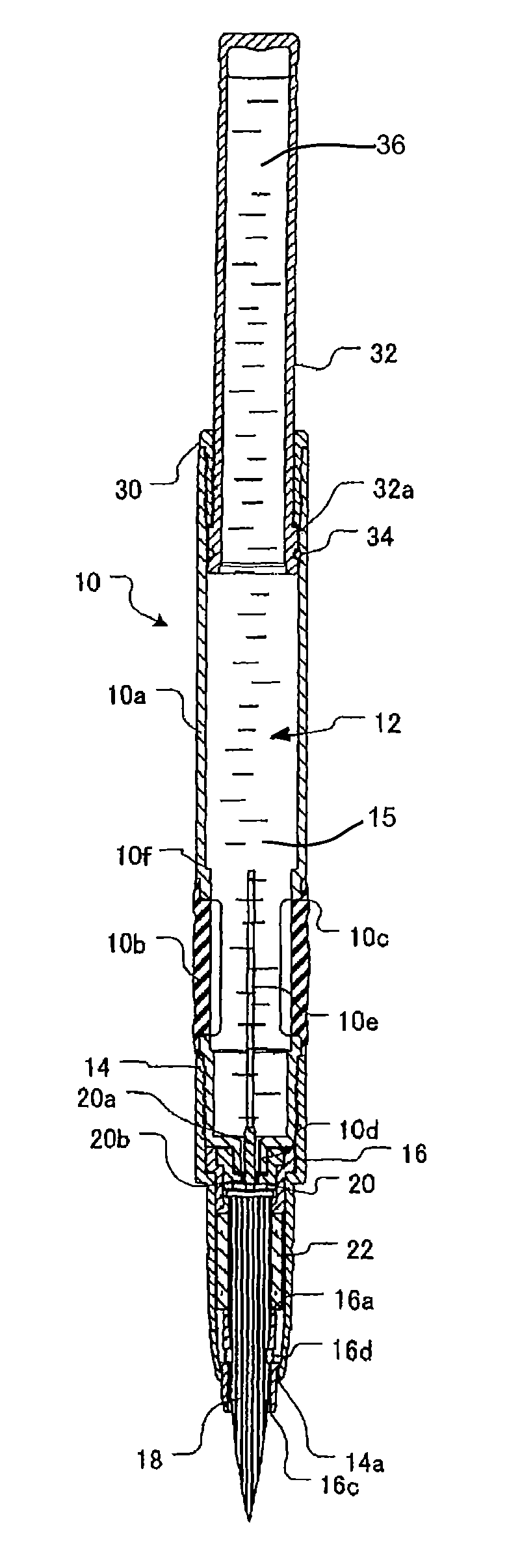
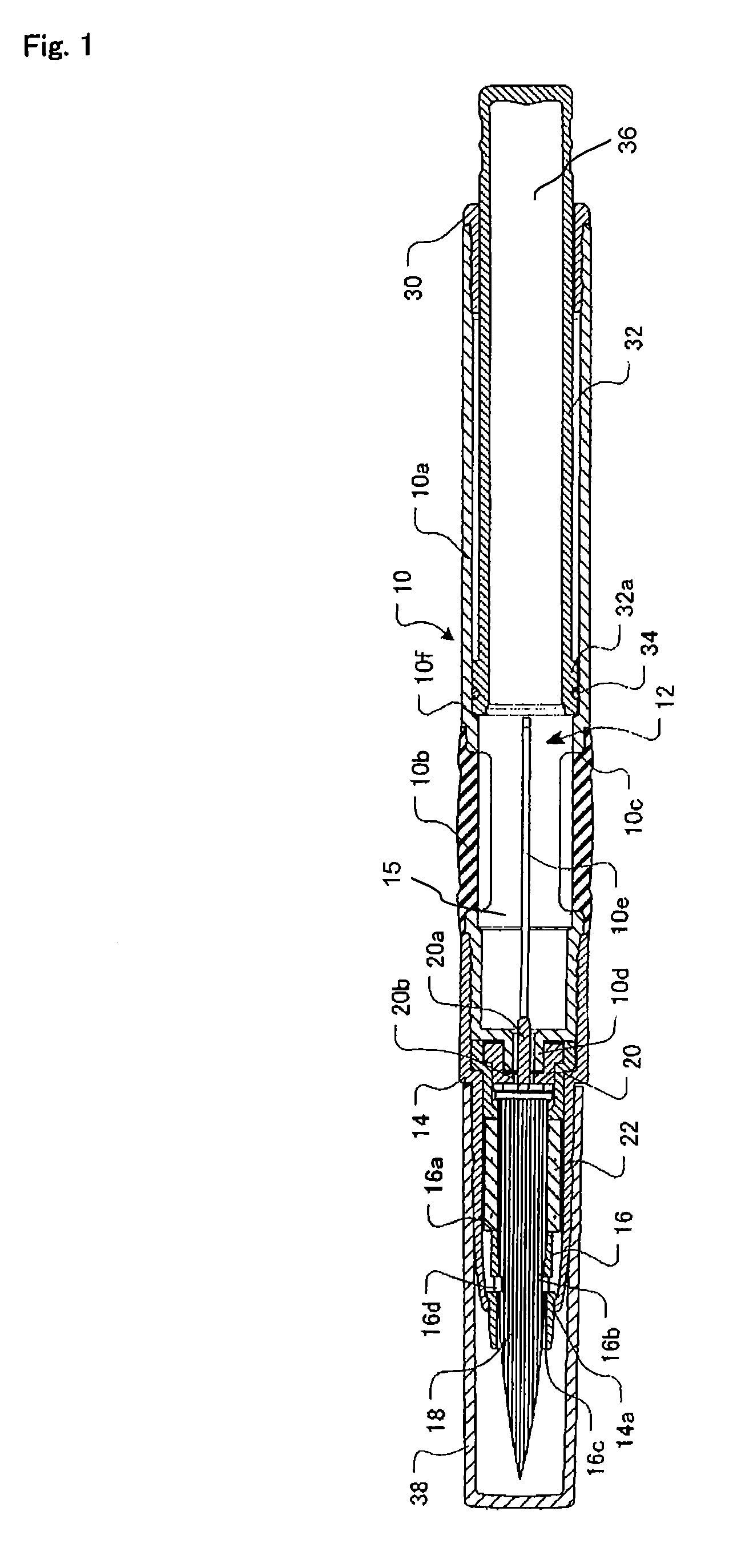
[0025]FIG. 1 is a whole longitudinal sectional view showing an embodiment of a liquid applicator according to the present invention. As shown inFIG. 1, a liquid applicator according to an embodiment of the present invention has a tank 12 for containing a liquid therein. The tank 12 comprises a first tank portion 15 and a second tank portion 36. The liquid applicator further has a main body 10 which includes a main body shaft portion 10a that is hard, and a flexible portion 10b that is soft and provided on a circumference of a part of the main body shaft portion 10a . The main body shaft portion 10a and the flexible portion 10b may be formed as separated members, or may be formed as an integrally molded member by two-color molding or insert molding.

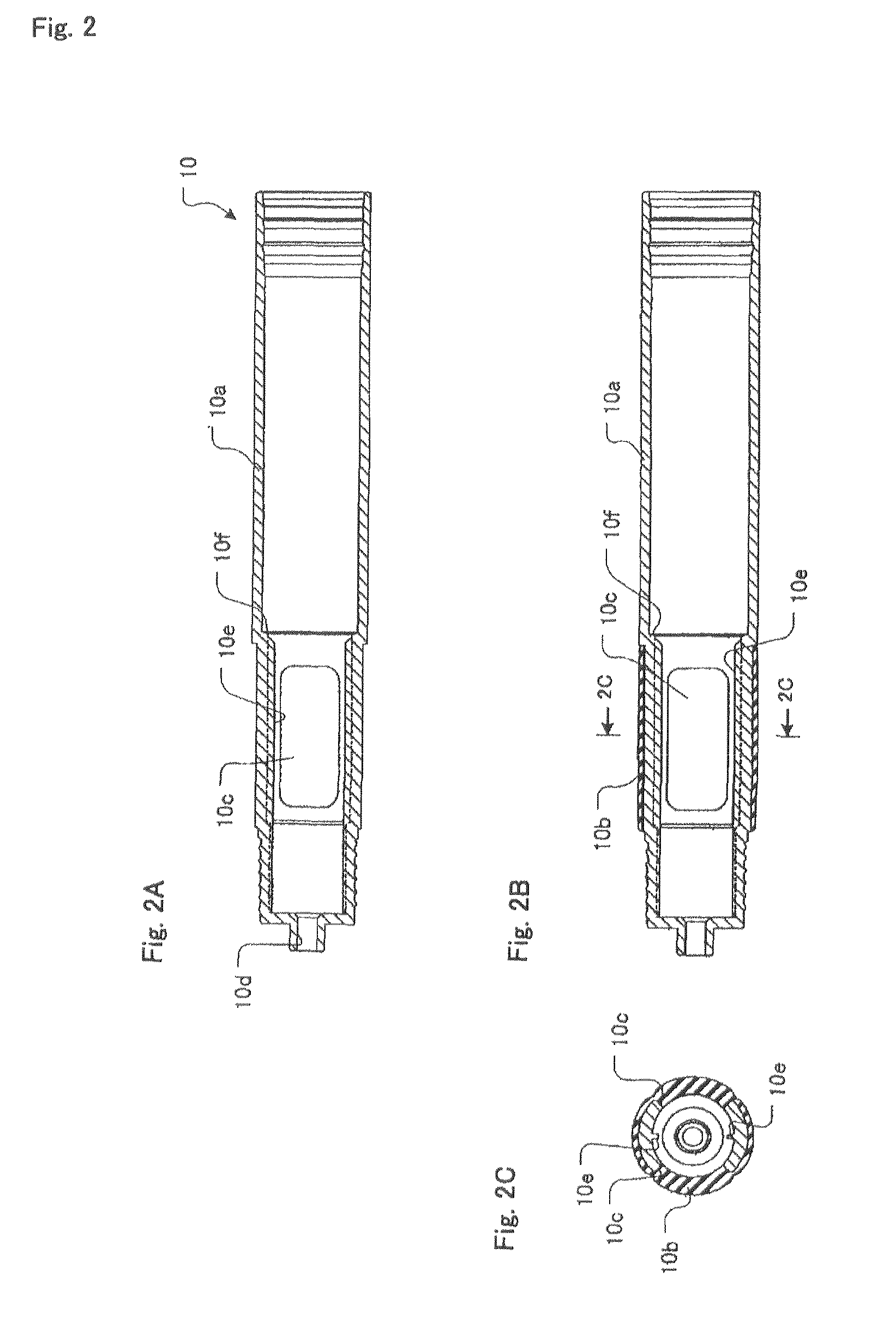
[0026]A side opening 10c is formed in the part of the main body shaft portion 10a where the flexible portion 10b is provided. The flexible portion 10b...


PUM


Abstract

There is provided a liquid applicator allowing a liquid to be easily replenished and replaced, as well as capable of containing a large amount of liquid. The liquid applicator includes a main body provided with a tank inside thereof, a tip shaft that is coupled to the tip end side of the main body, and a brush that is fixed in the tip shaft and projecting from the tip end of the tip shaft. A liquid may be sucked into a tank by releasing the coupling of the main body and the tip shaft, sinking a tip end opening of the main body in the liquid, and sliding a sliding cylinder attached to the rear portion of the main body.

Description

CROSS-REFERENCE TO RELATED APPLICATION[0001]This application is a U.S. National Phase of International Patent Application No. PCT / JP2008 / 050211, filed on Jan. 10, 2008, which claims priority under the Paris Convention to Japanese Patent Application No. JP 2007-004905, filed on Jan. 12, 2007.FIELD OF THE DISCLOSURE[0002]The present invention relates to a liquid applicator for applying a liquid and more particularly to a liquid applicator allowing a liquid to be freely replenished and replaced with another liquid.BACKGROUND OF THE DISCLOSURE[0003]A conventional liquid applicator contains a liquid to be applied in a tank provided inside thereof so that the liquid can be applied from a tip end applicator body on an object to be applied.[0004]In such conventional liquid applicator, a liquid in the tank cannot be replenished or replaced with another liquid. Therefore, it is not possible to change a type of the liquid in the tank and once the liquid runs out, there is no option but to thro...

Claims


Application Information

Patent Timeline
Patent Type & Authority Patents(United States)
IPC IPC(8): B43M11/06
CPCB43K8/03B43K11/00A46B2200/1046A46B11/0055B43K8/02B05C17/00
Inventor KAGEYAMA, HIDEHEINOGUCHI, YOSHIOSAWAYAMA, YOSHIYUKI
Owner KOTOBUKI & CO LTD
Why Eureka
Try Eureka