
Method of assembling emergency shelter panels including a bed platform

a technology of emergency shelter and platform, which is applied in the field of emergency shelter, can solve the problems of untraining, wet and unsanitary, and the internal support structure of the tent is difficult for ordinary people to assemble properly, and achieves the effect of easy recycling of materials

Inactive Publication Date: 2014-06-10
HUTTER GERHARD P
View PDF10 Cites 6 Cited by
  • Summary
  • Abstract
  • Description
  • Claims
  • Application Information

AI Technical Summary

Benefits of technology

The present invention is a novel and non-obvious emergency shelter assembly made up of eight plastic composite hollow-filled panels that are easy to assemble and portable. These panels have pre-formed holes and relieved portions for fast assembly in the field without tools. The shelter has a unique design with a raised roof panel and window and doorway, and incorporates solar cells or floor heating apparatus. Push anchors are used to quickly connect the panels together, and the shelter can be easily fastened to a pallet for easy transportation and assembly. The invention offers a simple and efficient solution for emergency shelters that can be quickly erected without significant assembly effort.

Problems solved by technology

Tents of the kind provided to refugees offer little protection from temperature extremes in cold or very hot climates.
The internal support structure of a tent can be difficult for ordinary, unskilled persons to assemble properly without training.
Tents usually have dirt floors which can be wet and unsanitary and a haven for vermin, insects and even unwanted reptiles.
Tents can also be expensive to manufacture depending upon the fabric used and the complexity of the mechanical structure needed to keep them up.
Therefore many shelters and alternative dwelling units have been invented or proposed but have not been successfully commercialized.
While such an idea may have merit for longer term use as habitations for displaced people, they would be impractical to use in many disaster situations as the cost, availability and difficulties associated with converting great numbers of units and then transporting such large structures to remote areas poses huge logistical problems.

Method used


Image

  • Method of assembling emergency shelter panels including a bed platform
  • Method of assembling emergency shelter panels including a bed platform
  • Method of assembling emergency shelter panels including a bed platform

Examples


Embodiment Construction

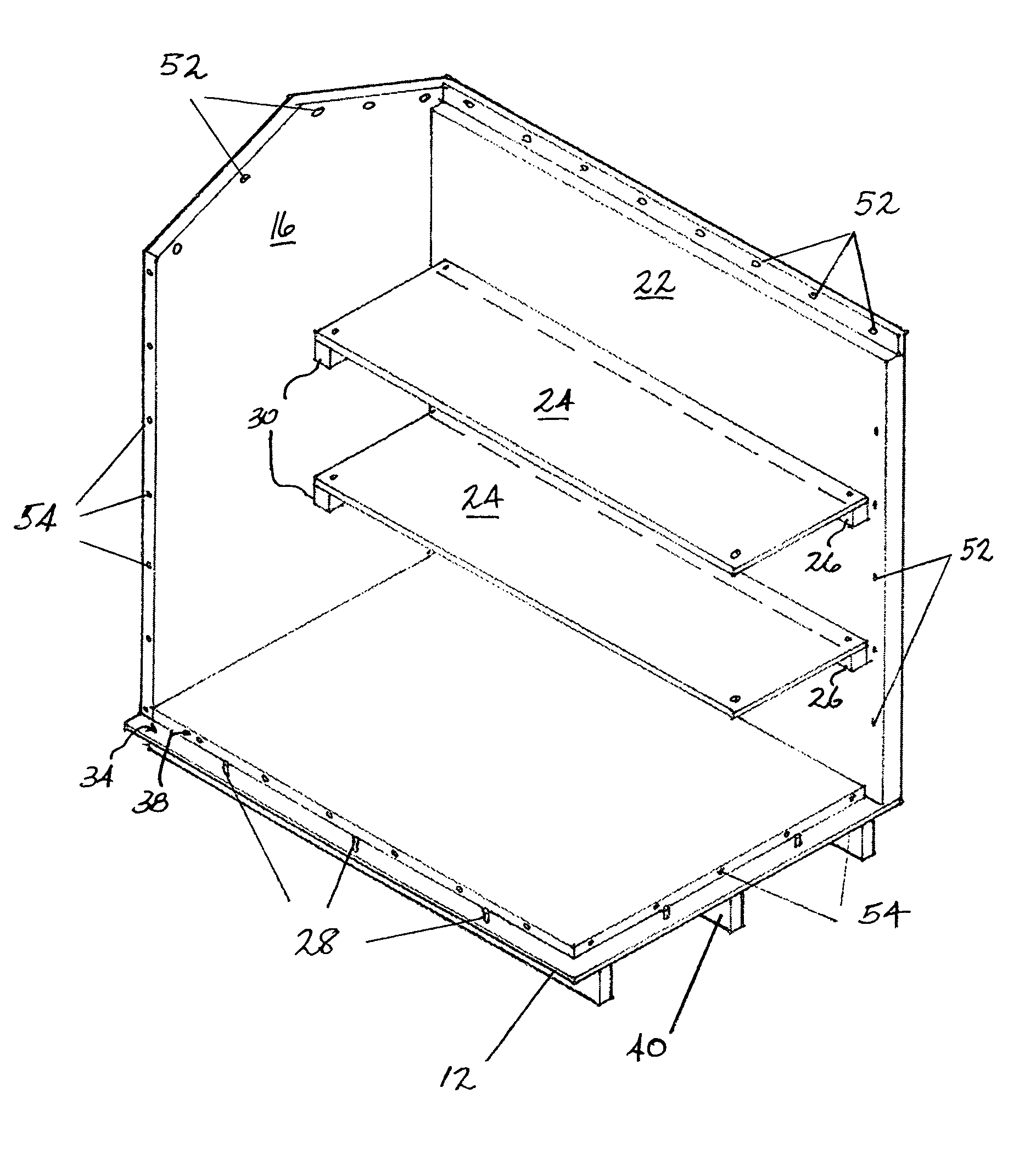
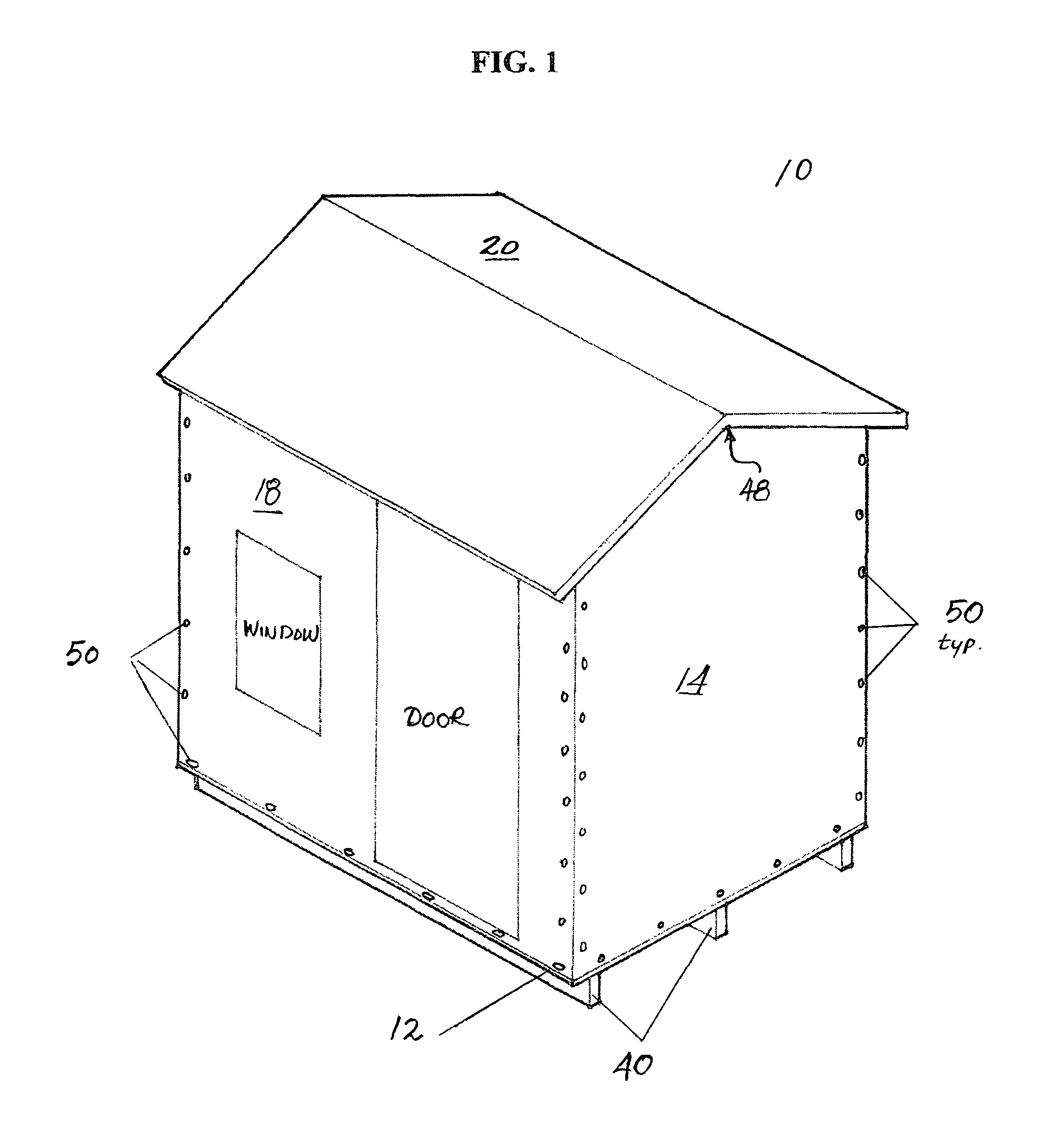
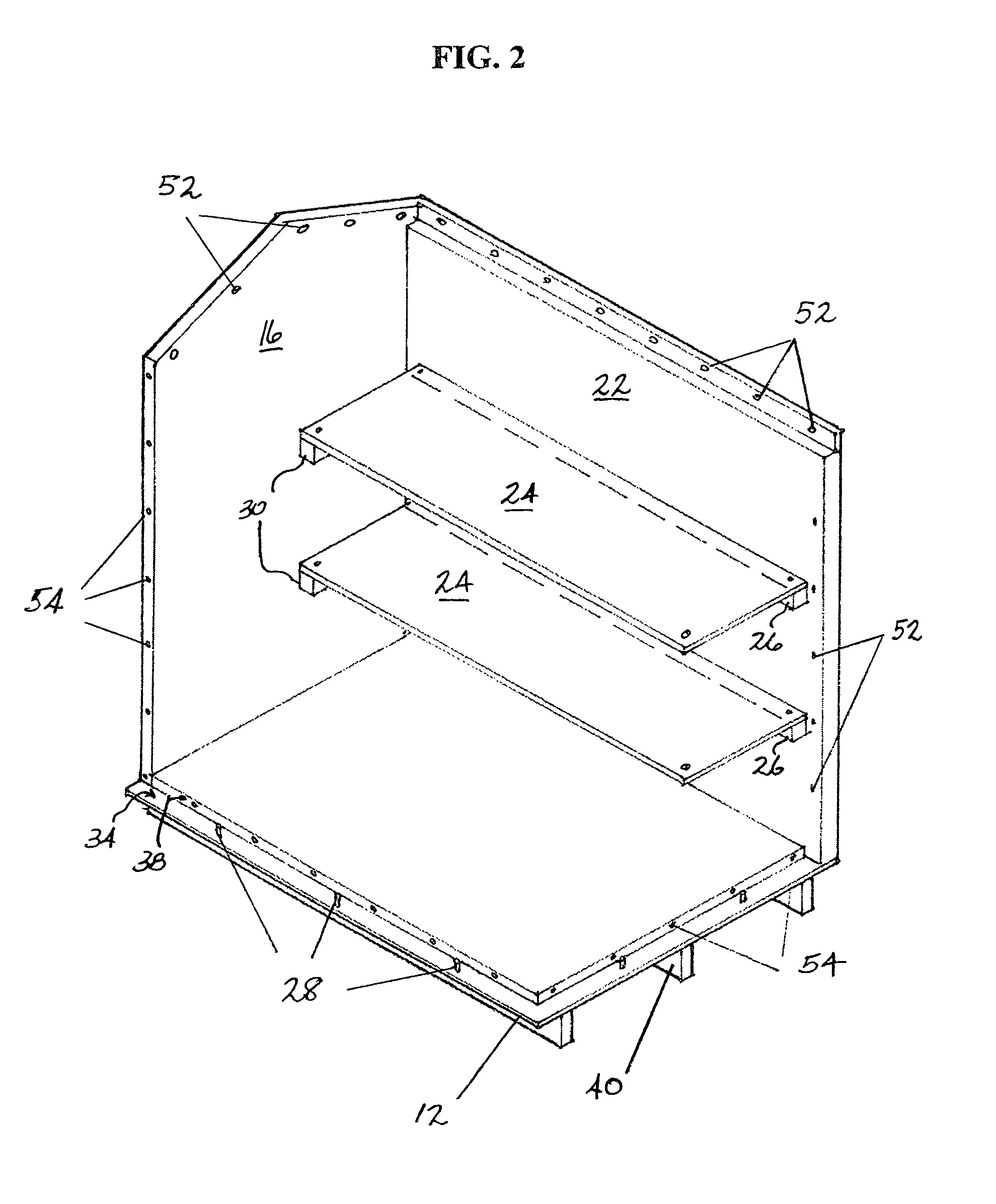
[0028]Referring to FIGS. 1 and 2, a housing unit assembled for use as an emergency shelter is illustrated generally at 10 in the present invention. The shelter is comprised of a front wall panel 18, two sidewall panels 14 and 16 respectively, a back wall panel 22, a roof panel 20, two bed platform panels 24 and a lower platform panel 12 which serves as the interior floor. In a preferred embodiment, the floor panel 12 also serves as the top surface of a rugged pallet for transporting the other panel sub-assemblies. The platform panel 12 of this preferred embodiment has a horizontal upper surface and lower skid-like projections, or risers, 40, which extend laterally along the underside of floor panel 12. The ends of three lateral risers 40 are visible in FIGS. 1 and 2. The lateral risers 40 are useful as a pallet for the sub-assemblies and also serve to keep the emergency shelter above the ground and free from flowing water.

[0029]Each panel sub-assembly is manufactured from plasticize...


PUM


Abstract

An emergency shelter structure is disclosed for use where people are displaced from their homes as the result of some catastrophe. The inventive shelter can be erected entirely without hand tools or power tools in less than 20 minutes. It is comprised of plastic panels which are joined together using push anchors, fasteners which permit rapid and permanent engagement of adjoining panels. Bed platforms are included as part of the assembly. In advanced embodiments, solar arrays are provided for harvesting solar energy for use as electricity and uni-directional heating apparatus is molded into the floor panel.

Description

CROSS REFERENCE TO RELATED APPLICATIONS[0001]The present application claims the priority of U.S. Provisional Patent Application Ser. No. 61 / 337,186, filed Feb. 1, 2010, entitled “EMERGENCY SHELTER.”STATEMENT REGARDING FEDERALLY SPONSORED RESEARCH AND DEVELOPMENT[0002]Not ApplicableREFERENCE TO SEQUENCE LISTING, A TABLE, OR COMPUTER PROGRAM LISTING COMPACT DISC APPENDIX[0003]Not ApplicableBACKGROUND OF THE INVENTION[0004]1. Field of the Invention[0005]The present invention relates to emergency shelters and specifically to emergency shelters provided to relieve suffering as a result of large scale disasters where many people are displaced from their homes. More specifically, the present invention discloses construction of short term sleeping quarters using pre-formed plastic panels enabling displaced persons to survive more safely and comfortably than they would if they were using more conventional facilities.[0006]2. Description of the Prior Art[0007]Typically, relief agencies and go...

Claims


Application Information

Patent Timeline
Patent Type & Authority Patents(United States)
IPC IPC(8): E04B1/343E04B1/35
CPCE04B1/355E04H9/16E04H1/12E04B1/34384E04H1/1205E04B1/34321E04B1/34315
Inventor HUTTER, GERHARD, P
Owner HUTTER GERHARD P
Learn More