
Vehicle bumper device

a bumper and vehicle technology, applied in the direction of bumpers, vehicle components, vehicular safety arrangments, etc., can solve the problem that the bumper reinforcement b>90/b> cannot efficiently absorb the energy of impact, and achieve the effect of bending strength and cross-sectional buckling strength of the bumper reinforcemen

Inactive Publication Date: 2014-06-10
AISIN SEIKI KK +1
View PDF24 Cites 16 Cited by
  • Summary
  • Abstract
  • Description
  • Claims
  • Application Information

AI Technical Summary

Benefits of technology

[0009]Accordingly, it is an objective of the present invention to provide a vehicle bumper device that is capable of increasing the bending strength of the center of the bumper reinforcement and the cross-sectional buckling strength of the end portions of the bumper reinforcement, without increasing the mass of the bumper reinforcement.
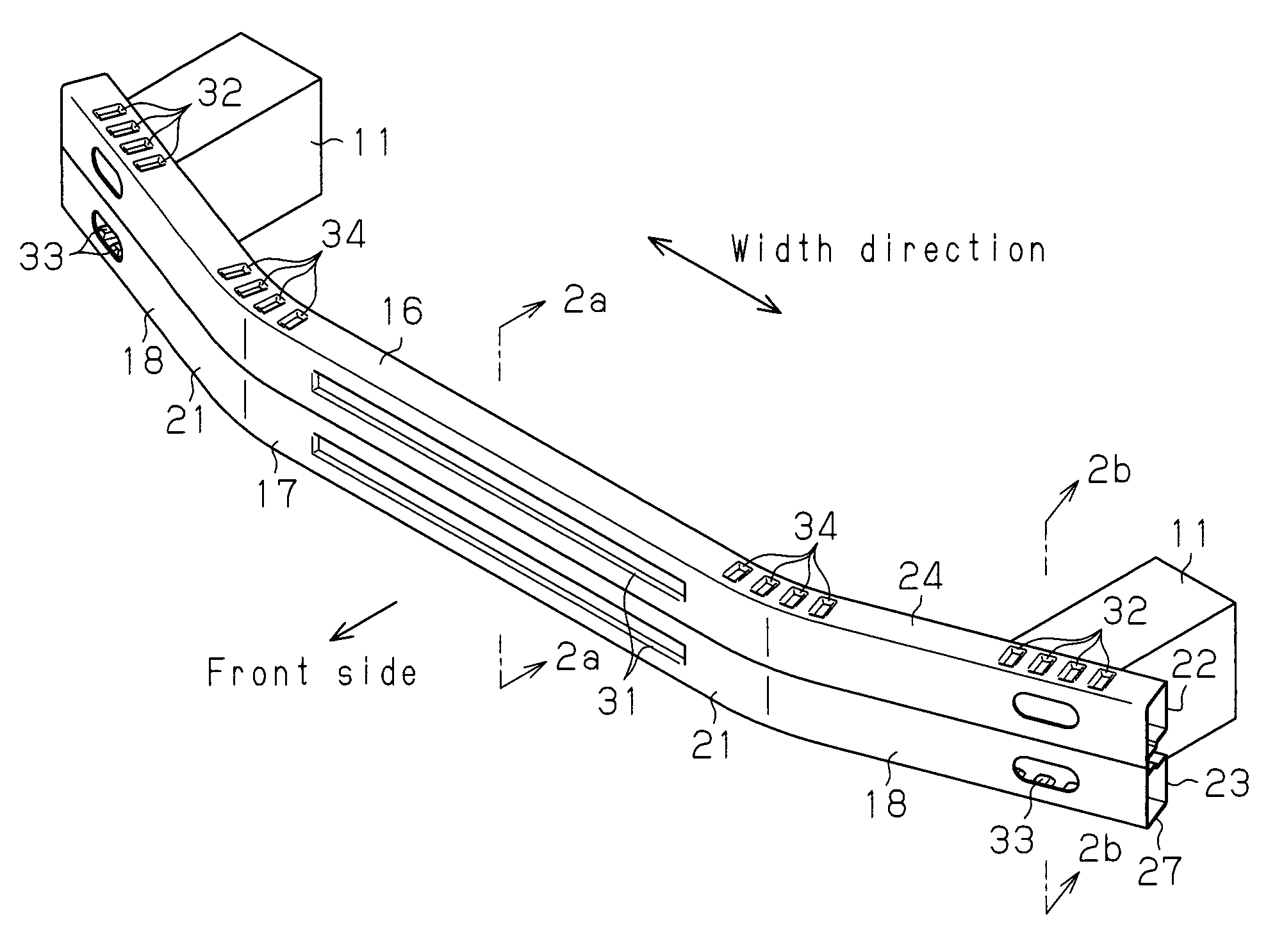
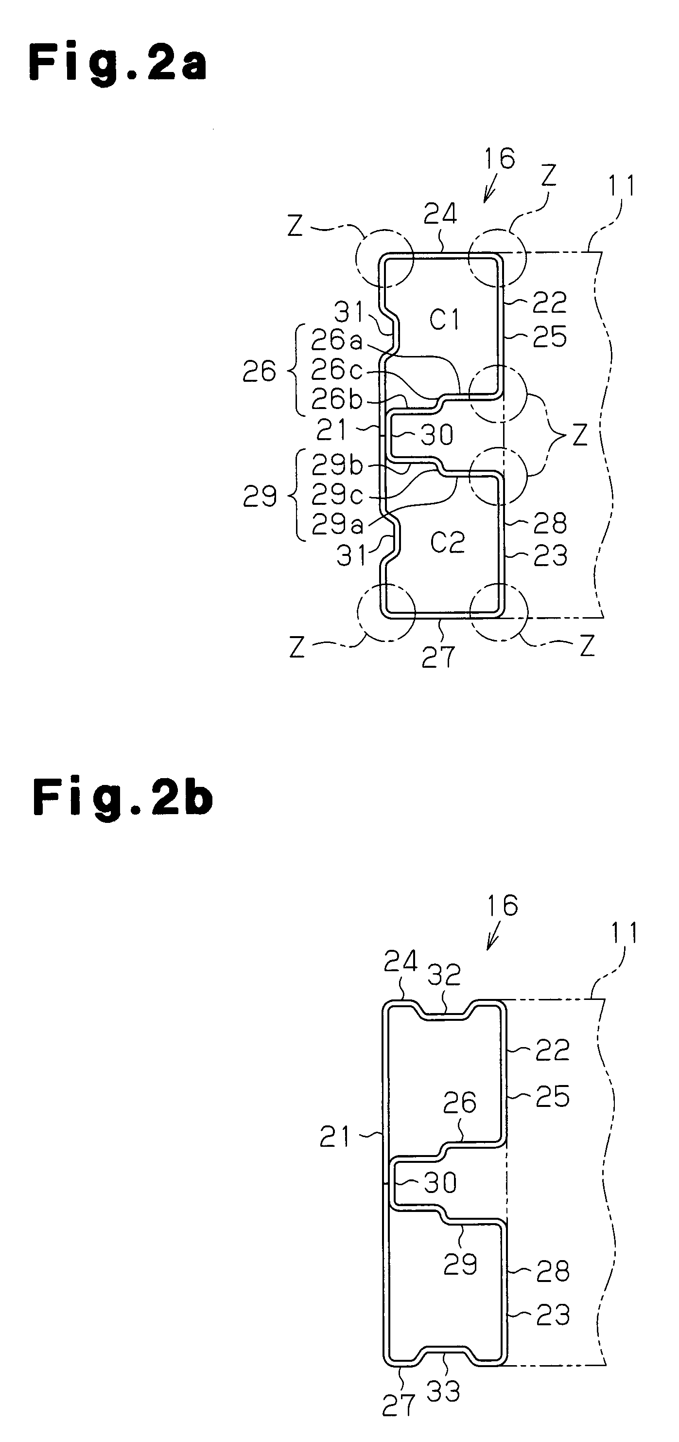
[0012]According to each of the above configurations, when load is applied in a concentrated manner to a center of the bumper reinforcement, which has the smallest strength, due to a collision with a pole, the bumper reinforcement is not easily broken because the rigidity of the outer wall portion is increased by the outer groove. Also, when load is evenly applied to an end portion of the bumper reinforcement due to an offset collision, the cross section of the end portion of the bumper reinforcement does not easily buckle because the rigidity of the upper and lower walls is increased is increased by the upper and lower grooves. Therefore, without increasing the thickness over the entire bumper reinforcement, the strength of each part is increased to a level sufficient for withstanding the corresponding type of collision.
[0014]According to this configuration, the steps formed on the opposing walls shorten the buckle wavelength of the opposing walls, and the buckling strength of the bumper reinforcement is increased, accordingly.
[0016]According this configuration, the bumper reinforcement has two bends. Thus, at a collision with a vehicle having a flat front end or a flat rear end, the load applied to the straight portion of the bumper reinforcement from the front is evenly dispersed in the straight portion. This prevents the load from being concentrated on a single part of the bumper reinforcement and from breaking the part.
[0018]According to this configuration, compared to a case in which the radius of curvature is greater than 5 mm, the bending strength and the cross-sectional buckling strength of the bumper reinforcement are both increased.

Problems solved by technology

As a result, the bumper reinforcement 90 cannot efficiently absorb the energy of impact.

Method used


Image

  • Vehicle bumper device
  • Vehicle bumper device
  • Vehicle bumper device

Examples


Embodiment Construction

[0023]A vehicle bumper device according to one embodiment of the present invention will now be described. In this embodiment, the vehicle bumper device is applied to a vehicle front portion.

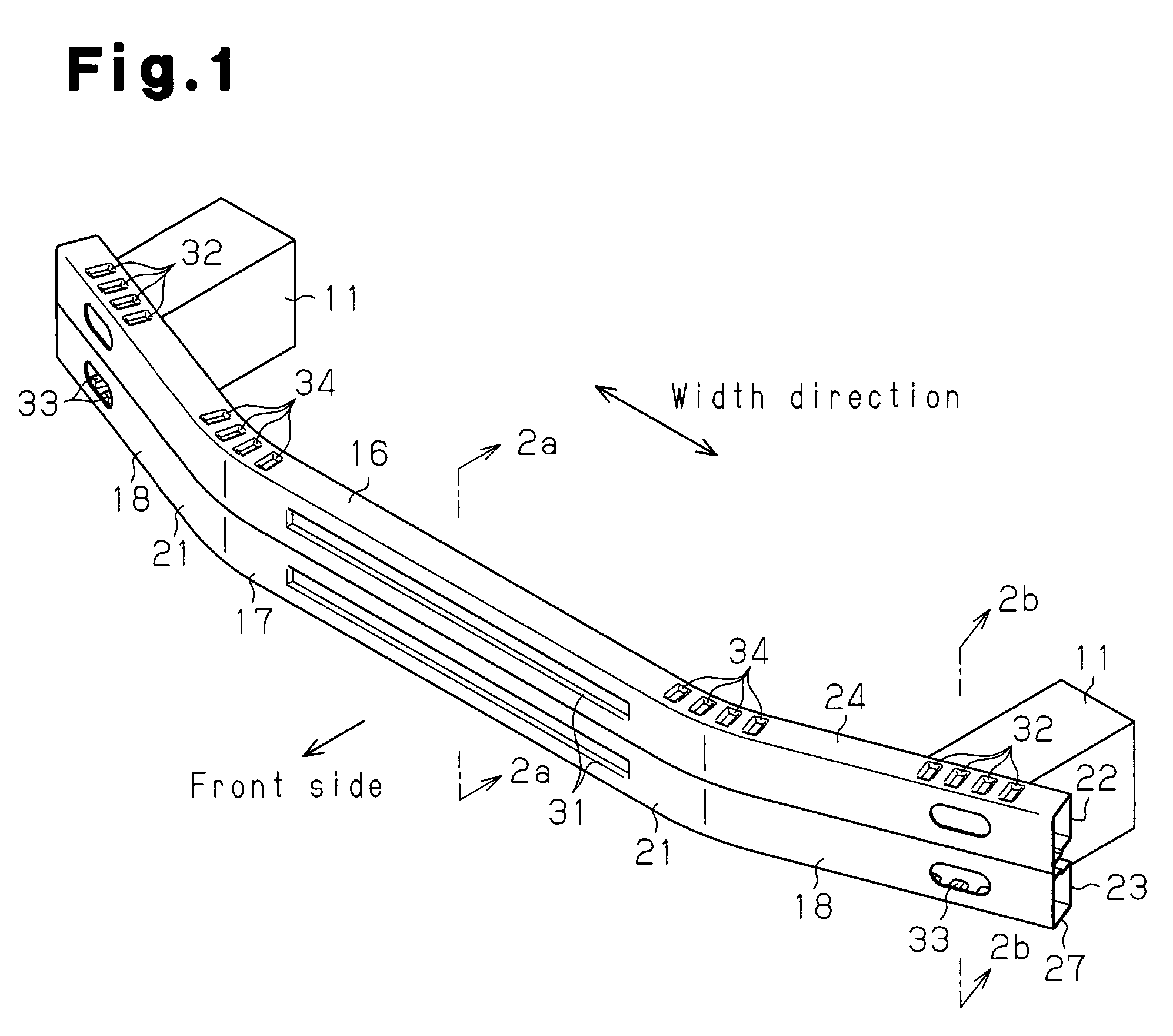
[0024]As shown in FIG. 1, a vehicle has a pair of side members 11, which serve as coupling members. Each side member 11 is located on one side of the vehicle. The side members 11 are formed by metal plates. The side members 11 have a hollow structure with a substantially rectangular cross-section. The side members 11 extend in the front-rear direction of the vehicle. The side members 11 form a part of the vehicle body. The front end of each side member 11 is connected to one end of a bumper reinforcement 16 via a bracket (not shown). The bumper reinforcement 16 extends in the width direction of the vehicle. The bumper reinforcement 16 is formed by a metal plate obtained through roll forming, for example, a steel plate of approximately 1500 MPa. The bumper reinforcement 16 has a substantially cons...


PUM


Abstract

A bumper reinforcement includes a front wall portion, an upper wall portion, and a lower wall portion. The front wall portion constitutes the front portion of the bumper reinforcement. The upper wall portion constitutes the upper half of the rear portion of the bumper reinforcement. The lower wall portion, connected to the lower edge of the front wall portion, constitutes the lower half of the rear portion. Outer grooves, formed by denting the front wall portion rearward, extend along the vehicle width direction. Upper grooves, formed by denting downward a top wall of the upper wall portion, are located intermittently along the width direction and extend in the longitudinal direction. The lower wall portion comprises a bottom wall constituting the bottom of the lower wall portion. Lower grooves, formed by denting the lower wall portion upward, are located intermittently along the width direction and extend in the longitudinal direction.

Description

CROSS-REFERENCE TO RELATED APPLICATIONS[0001]This application is a national phase application of International Application No. PCT / JP2010 / 069517, filed Nov. 2, 2010, and claims the priority of Japanese Application No. 2009-254070, filed Nov. 5, 2009, the contents of both of which are incorporated herein by reference.FIELD OF THE INVENTION[0002]The present invention relates to a vehicle bumper device.BACKGROUND OF THE INVENTION[0003]A vehicle bumper device includes a bumper reinforcement, which extends in the direction of the width of a vehicle. Each end portion of the bumper reinforcement is coupled to one of a pair of coupling members (for example, side members), which extends in the front-rear direction of the vehicle.[0004]The bumper reinforcement disclosed in Patent Document 1 is formed by a high-tensile steel plate, which is obtained through roll forming. The bumper reinforcement has a constant cross-sectional shape along the longitudinal dimension thereof. The bumper reinforce...

Claims


Application Information

Patent Timeline
Patent Type & Authority Patents(United States)
IPC IPC(8): B60R19/04
CPCB60R2019/1813B60R19/18B60R19/12
Inventor HANEDA, SHINICHIKITA, KIYOICHISHOBO, JUNOBAYASHI, TAMAKI
Owner AISIN SEIKI KK
Learn More