Luminaire and optical component

a technology of optical components and luminaires, applied in the field of lighting, can solve the problems of requiring quite high optics requirements for led lighting use, utilizing point sources of light present challenges for developers and providers of products, etc., and achieve the effect of increasing the probability and enhancing the control of light beams

Active Publication Date: 2014-06-10
KONINKLIJKE PHILIPS ELECTRONICS NV
View PDF10 Cites 0 Cited by
  • Summary
  • Abstract
  • Description
  • Claims
  • Application Information

AI Technical Summary

Benefits of technology

[0007]In view of the above, it would therefore be desirable to achieve an improved luminaire. In particular, it would be advantageous to achieve a luminaire having improved mixing properties and which reduces beam inhomogeneities.
[0009]Beneficially, light may be refracted mainly in the angular or azimuth direction with respect to the beam due to the radially extending refractive structures. Thereby light in the azimuth direction may be smeared out, and mixing of light in the azimuth direction may be enhanced. This may be in particular be advantageous when shaping light from several light sources of a lighting device (such as a luminaire) distributed around the optical axis of the lighting device. Further, requirements on the internal optics of the lighting device, such as diffusers and mixing cavities may be reduced and / or the aforesaid optical components may be excluded from the lighting device. Thereby, a more cost efficient and simpler lighting device may be provided.
[0019]Thereby enhanced control of the light beam may be achieved when the light first enters the dense medium via a planar surface, and is refracted when going to air. In contrast, if the light is first refracted by the refractive structures, and then by the planar surface, light rays have a larger probability to have TIR (Total Internal Reflection) at the first side (e.g. the planar surface), and stay inside the material (and hence get scattered uncontrollably).
[0020]The luminaire may comprise a plurality of light sources, each light source being located at least at a distance d from an optical axis O of said luminaire, wherein a radius r of said optical component is at least as large as said distance d. Hence each light source may be refracted efficiently by the optical component.

Problems solved by technology

In many applications, utilizing point sources of light present challenges for developers and providers of products thereof.
However, the use of LEDs in general lighting has required quite high demands on the optics used because of e.g. the high brightness provided by the LEDs.

Method used


Image

  • Luminaire and optical component
  • Luminaire and optical component
  • Luminaire and optical component

Examples


Embodiment Construction

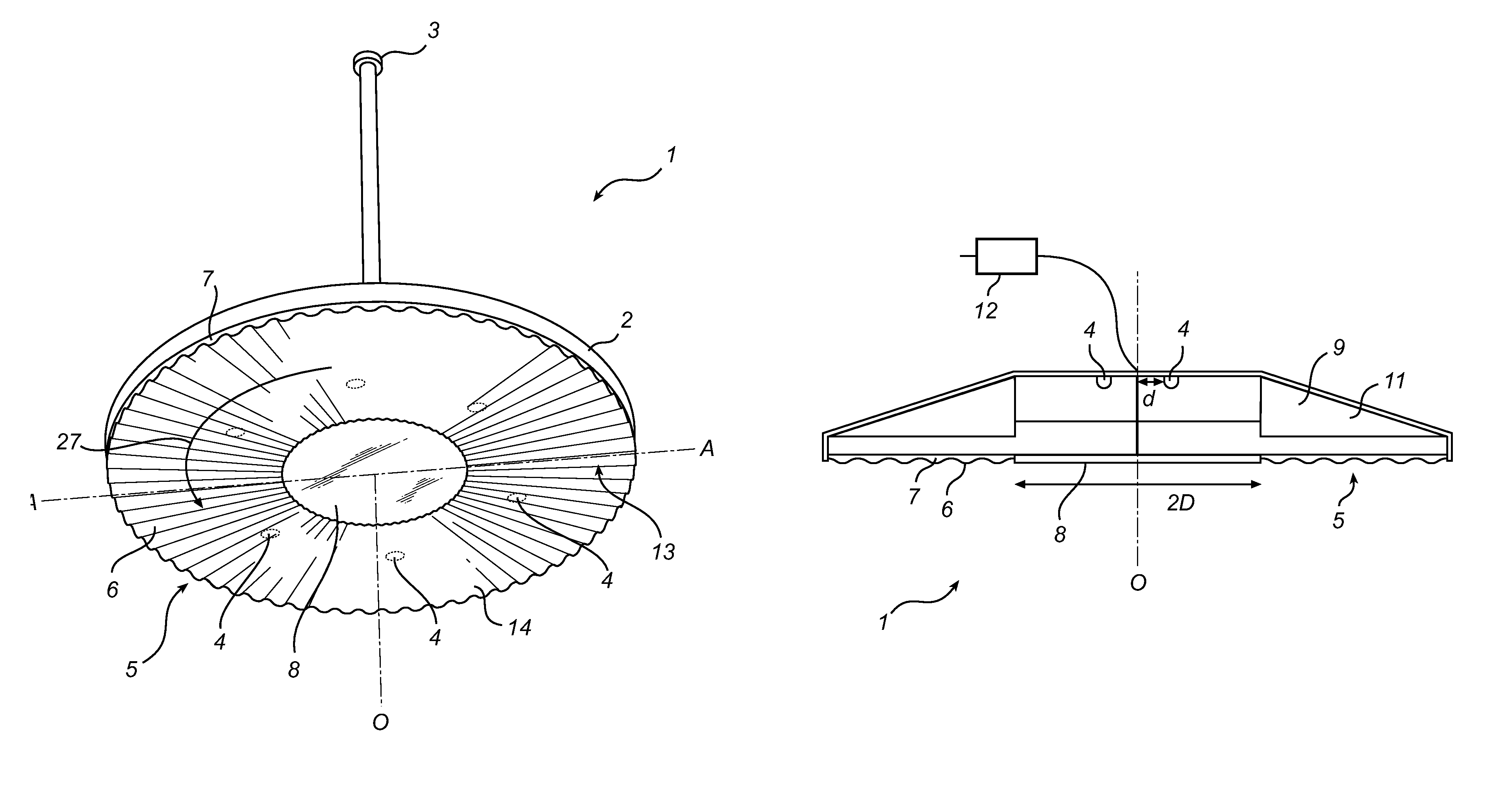
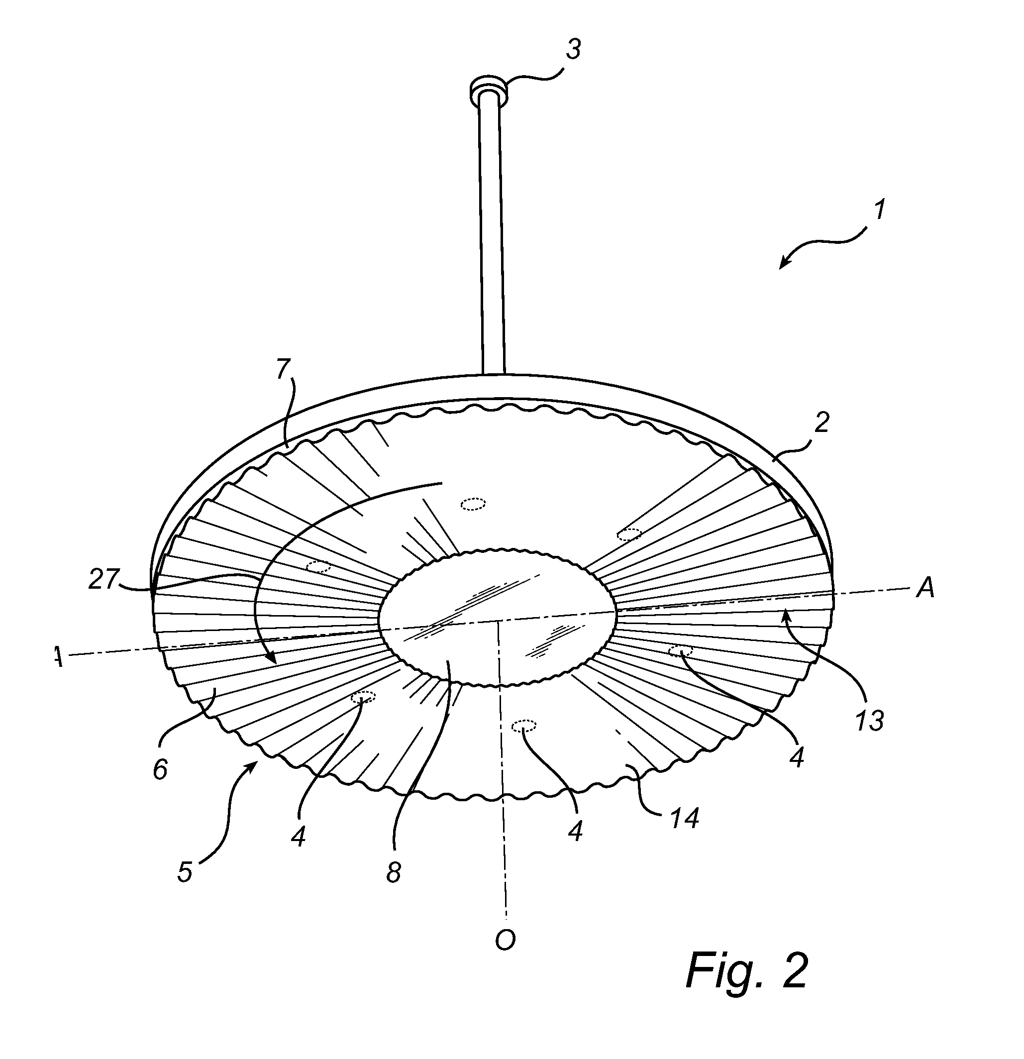
[0031]With reference to FIG. 2, an embodiment of a luminaire 1 in accordance with the present invention is shown. The luminaire 1 comprises inter alia a housing 2, a socket 3, a cap 8, a plurality of light sources 4, which throughout the description will be exemplified by LEDs, and an optical component 5. In operational use of the luminaire 1, the optical component 5 provides an exit window for light emanating from the LEDs 4. More specifically, the optical component 5 has a refractive side 14 presenting a refractive surface 13 comprising a plurality of radially extending refractive structures 6 forming an undulating pattern 7 in an angular direction 27 on the refractive surface 13.

[0032]By means of the refractive structures 6 a light beam emanating from the plurality of LEDs can be mixed in an efficient way in the angular direction 27, referred to as the azimuth direction herebelow, of the refractive surface 13.

[0033]Beneficially, by placing the optical component 5 at a distance fr...


PUM


Abstract

It is presented an optical component (5) a first side (30) and a refractive opposite side (14). The refractive side (14) presents a refractive surface (13) and has radially extending refractive structures (6) for refracting light mainly in the azimuth direction (27) of an inciding light beam. The optical component (5) can be used as an exit window in a luminaire (1) having at least one light source (4), whereby light inhomogeneity may be reduced.

Description

FIELD OF THE INVENTION[0001]The technical field of the present invention is lighting. In particular, the present invention relates to an optical component and a luminaire.BACKGROUND OF THE INVENTION[0002]In many applications, utilizing point sources of light present challenges for developers and providers of products thereof. Examples of point sources are for instance different type of semiconductor light sources such as LEDs and OLEDs.[0003]Further development of LEDs (Light Emitting Diodes) e.g. higher luminance, have opened new areas for their use. For instance, LEDs may nowadays be utilized in general lighting applications such as luminaires. Thereby the advantages provided by LED technology, such as narrow bandwidth lighting, enhanced control, and low energy consumption, may be utilized in previously unexplored fields of use.[0004]However, the use of LEDs in general lighting has required quite high demands on the optics used because of e.g. the high brightness provided by the L...

Claims


Application Information

Patent Timeline
Patent Type & Authority Patents(United States)
IPC IPC(8): F21V5/02
CPCF21V5/00F21Y2101/02F21V5/02G02B6/0038F21Y2115/10H01L33/58
Inventor VISSENBERG, MICHEL CORNELIS JOSEPHUS MARIEKRIJN, MARCELLINUS PETRUS CAROLUS MICHAELUITBEIJERSE, BASTIAAN
Owner KONINKLIJKE PHILIPS ELECTRONICS NV
Why Eureka
Try Eureka