Supercharge Your Innovation With Domain-Expert AI Agents!

Float switch

a technology of float switch and switch body, which is applied in the direction of mangetic float movement actuation, dynamo-electric converter control, relays, etc., can solve the problems of poor waterproof performance of products, poor sealing property of mechanical switches, and long service life of complex mechanical structures. , to achieve the effect of long service life, high reliability and simple control circui

Active Publication Date: 2014-06-10
GP ENTERPRISES CO LTD
View PDF9 Cites 0 Cited by
  • Summary
  • Abstract
  • Description
  • Claims
  • Application Information

AI Technical Summary

Benefits of technology

The invention aims to provide a float switch with a long service life and high reliability. The circuit includes a voltage-dropping power supply part, a detection part for dry reed pipes, a control part for on-off control of the relay and a relay driving and protection part for protecting the relay from damage. The control circuit is simple, low-cost, reliable, and can work under great fluctuations in voltage. The product is excellent in waterproof performance, has a simple and low-mounting process, and reduced fraction defective and scrappage rate, resulting in lower costs.

Problems solved by technology

Generally, the mechanical switches are not good in sealing property and not long in service life.
The complex mechanical structures are not ideal in reliability.
Products are poor in waterproof performance, the misgiving about the situation that moisture may enter into the products can not be completely avoided, and the metal oxidation phenomenon may occur.
The products are complex in production and mounting and high in fraction defective and scrappage rate so as to cause the high cost of the products.

Method used


Image

  • Float switch
  • Float switch
  • Float switch

Examples


Embodiment Construction

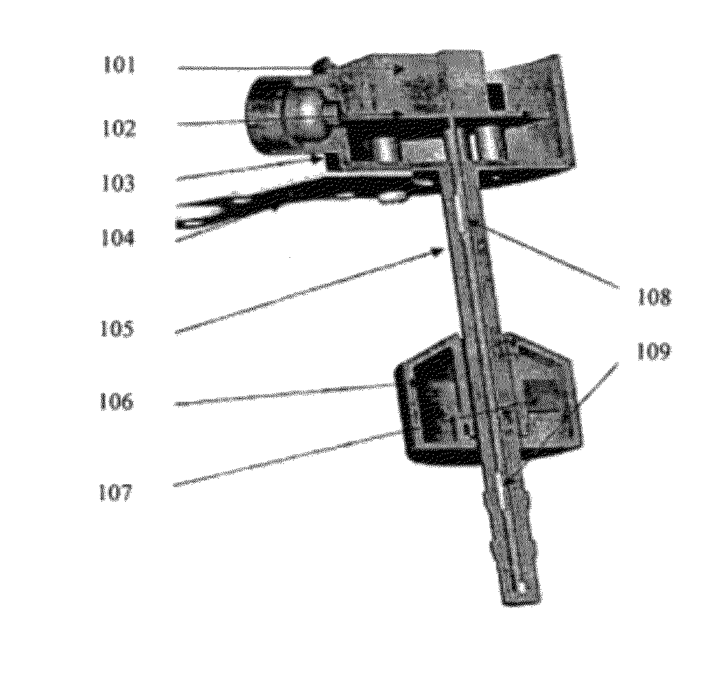
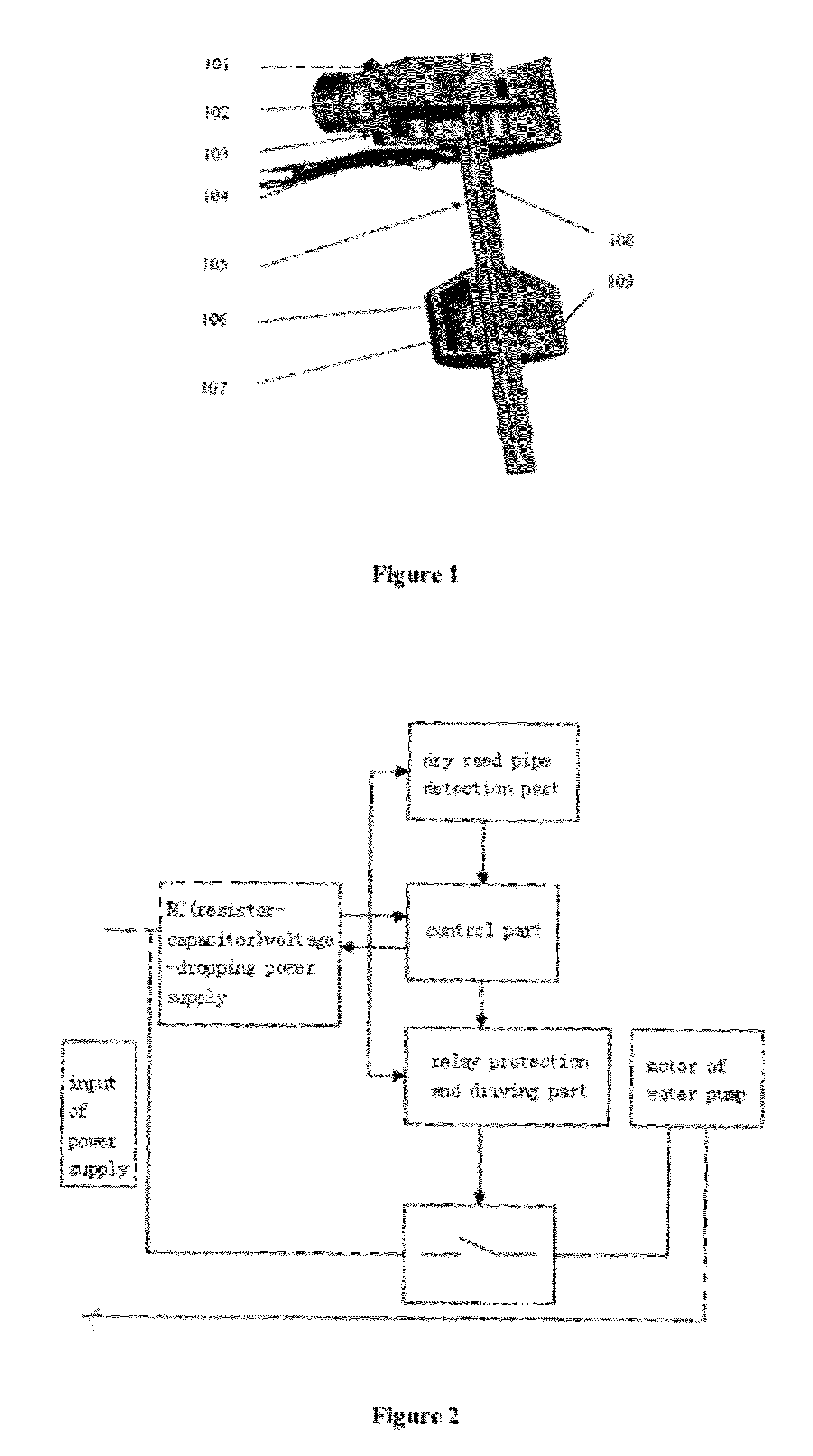
[0014]As shown in FIG. 1, a float switch of the invention comprises a float 106, a float guide rod 105, a dry reed pipe detection device and a relay 101. The float 106 is sheathed on the float guide rod 105 and can slide freely. The dry reed pipe detection device comprises a high-level dry reed pipe 108, a low-level dry reed pipe 109 and a magnet 107. The interior of the float guide rod 105 is hollow. The high-level dry reed pipe 108 and the low-level dry reed pipe 109 are arranged at the high level and the low level in the float guide rod respectively. The magnet 107 is arranged in the float 106. When the water level is low, the height of the float is also low. The low-level dry reed pipe 109 is switched on due to attraction of the magnet, the high-level dry reed pipe 108 can not be switched on because the high-level dry reed pipe 108 is farther away from the magnet, and the relay 101 is further switched off through the control of a circuit at this time. When water is slowly inject...


PUM


Abstract

A float switch includes a floater (106), a float leader (105), a reed pipe detection device and a relay (101). The floater (106) is sleeved on the float leader (105), and can slide freely. The reed pipe detection device comprises a high-level reed pipe (108), a low-level reed pipe (109) and a magnet (107). The float leader (105) is hollow. The high-level reed pipe (108) and the low-level reed pipe (109) are located in a high level and a low level inside the float leader (105) respectively. The magnet (107) is provided inside the floater (106). A motor is controlled by the relay (101) in the float switch. The motor begins to work when the relay (101) is switched on, and the motor stops working when the relay (101) is switched off. The switch has a long service life, high reliability and an excellent waterproof property. The float switch has a simple manufacture and installation process, less fraction defective and condemnation factor, thus further reduces the cost.

Description

TECHNICAL FIELD[0001]The present invention relates to a float switch, and specifically relates to a float switch for a water pump, which belongs to the technical field of fluid engineering.BACKGROUND OF THE INVENTION[0002]In the prior art, float switches for water pumps use mechanical switches. Generally, the mechanical switches are not good in sealing property and not long in service life. The complex mechanical structures are not ideal in reliability. Products are poor in waterproof performance, the misgiving about the situation that moisture may enter into the products can not be completely avoided, and the metal oxidation phenomenon may occur. The products are complex in production and mounting and high in fraction defective and scrappage rate so as to cause the high cost of the products.SUMMARY OF THE INVENTION[0003]Against the existing technical problems, the invention aims at providing a float switch with long service life and high reliability.[0004]The technical solution of ...

Claims


Application Information

Patent Timeline
Patent Type & Authority Patents(United States)
IPC IPC(8): H02P23/00H02P1/44H02P1/42
CPCH01H36/006H01H36/0006H01H36/02
Inventor WANG, LIMING
Owner GP ENTERPRISES CO LTD
Features
  • R&D
  • Intellectual Property
  • Life Sciences
  • Materials
  • Tech Scout
  • Unparalleled Data Quality
  • Higher Quality Content
  • 60% Fewer Hallucinations
Learn More