
Method for transmitting ranging information in wireless communication system and terminal thereof

a wireless communication system and wireless communication technology, applied in the direction of data switching network, wireless commuication services, transmission path division, etc., can solve the problem of length not known, achieve the effect of effective configuration of a particular channel, and enhance channel performance and resource efficiency

Active Publication Date: 2014-06-10
LG ELECTRONICS INC
View PDF45 Cites 9 Cited by
  • Summary
  • Abstract
  • Description
  • Claims
  • Application Information

AI Technical Summary

Benefits of technology

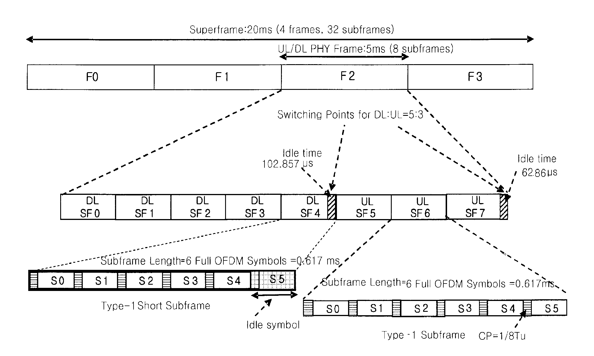
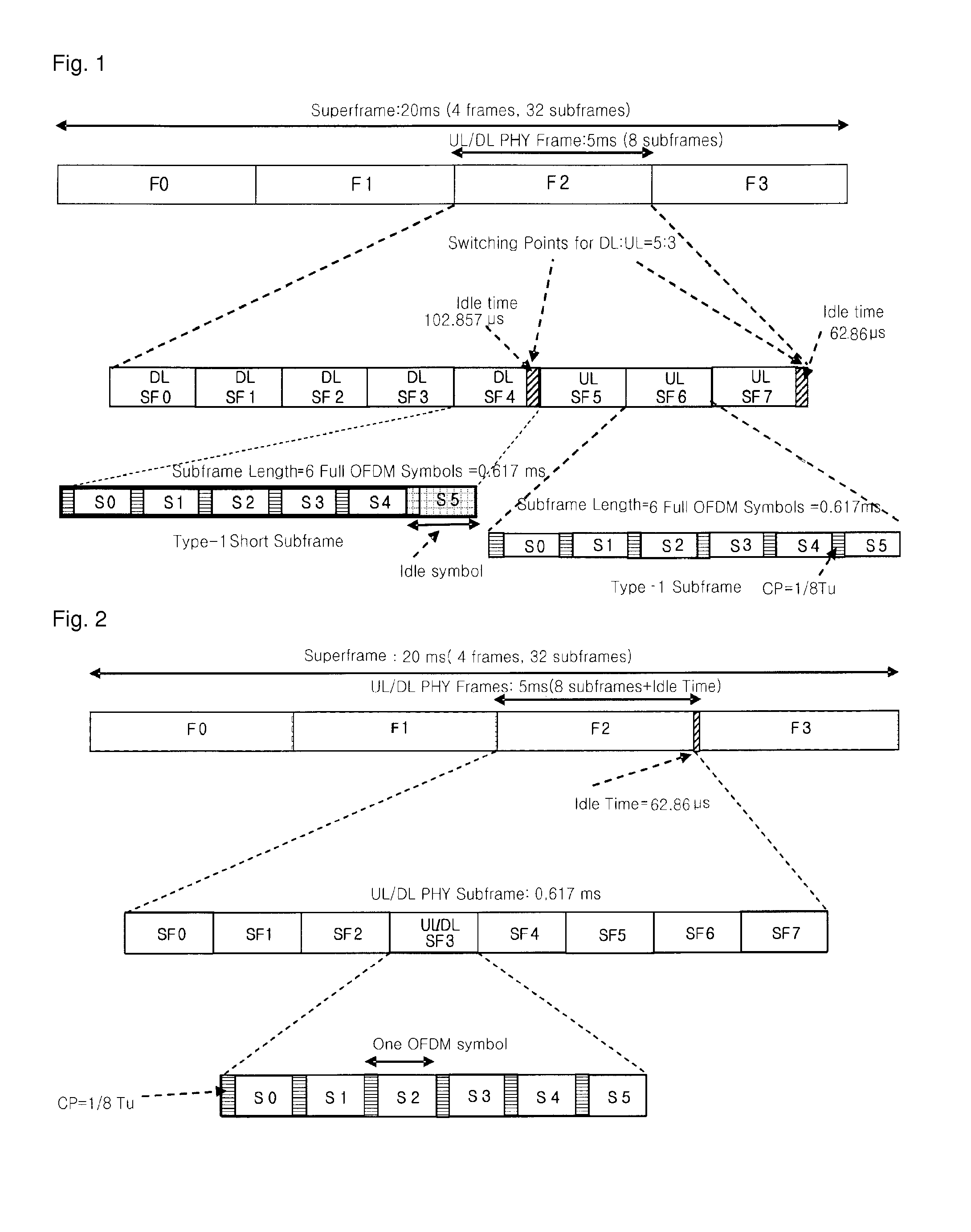
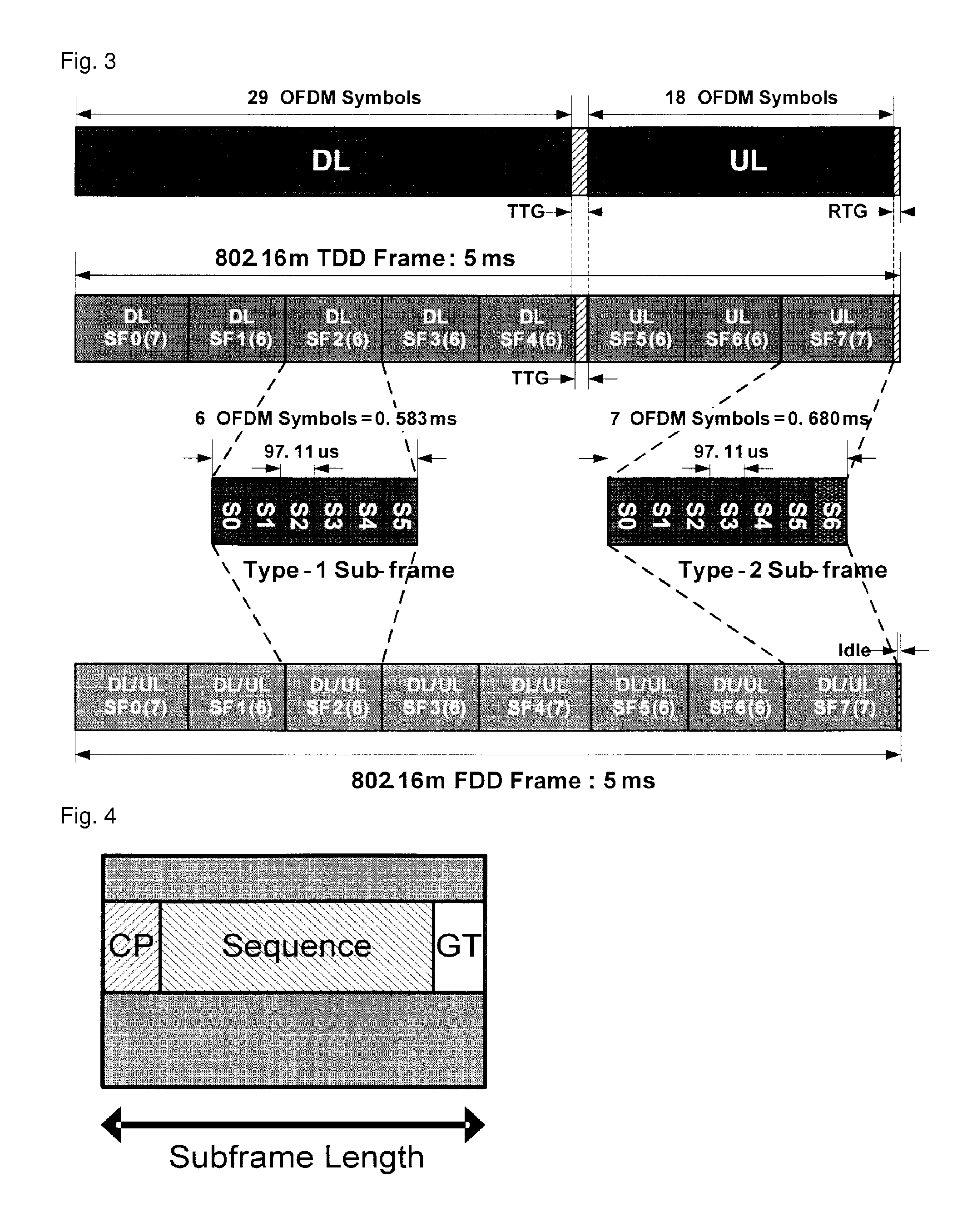
The present invention improves the performance and efficiency of a wireless communication system by using certain time intervals in a frame structure as a ranging channel. These time intervals, such as idle time and idle symbols, are not typically used for data transmission. By utilizing these intervals, the system's channel performance and resource efficiency can be enhanced. Additionally, the ranging channel may include a guard band to prevent interference with adjacent channels. This innovation leads to improved overall performance and efficiency of wireless communication systems.

Problems solved by technology

However, the message is generated between the BS and the MS for a capability negotiation during an initial network entry procedure, and the length cannot be known in the state that the MS initially transmits a ranging code to the BS.

Method used


Image

  • Method for transmitting ranging information in wireless communication system and terminal thereof
  • Method for transmitting ranging information in wireless communication system and terminal thereof
  • Method for transmitting ranging information in wireless communication system and terminal thereof

Examples


Embodiment Construction

[0066]The present invention is applied to a method for configuring a frame structure and a ranging channel. However, without being limited thereto, the present invention can be also applicable to any data structure configuring method and wired / wireless communication system to which the technical ides of the present invention is applied.

[0067]The present invention may be modified variably and may have various embodiments, particular ones of which will be illustrated in drawings and described in detail. However, it should be understood that the following exemplifying description of the invention is not meant to restrict the invention to specific forms of the present invention but rather the present invention is meant to cover all modifications, similarities and alternatives which are included in the spirit and scope of the present invention.

[0068]While such terms as “first” and “second,” etc., may be used to describe various components, such components must not be limited to the above...


PUM


Abstract

Disclosed is a method for configuring a ranging channel in various frame structures and using the same in a communication system. A ranging channel is effectively configured according to a data structure, namely, frame structure, transmitted and received between a mobile station (MS) and a base station (BS) in a wireless communication system, and ranging information is transmitted therethrough to thereby improve performance of a communication channel and resource efficiency. In the wireless communication system, a ranging channel is configured by using a time interval, such as an idle time, an idle symbol, an RTG, a TTG, and the like, not actually used for transmission of data or a signal in a data structure, namely, in a frame structure, transmitted and received between an MS and a BS, to transmit ranging information, so the channel performance and resource efficiency can be improved.

Description

CROSS-REFERENCE TO RELATED APPLICATIONS[0001]This application is the National Stage filing under 35 U.S.C. 371 of International Application No. PCT / KR2010 / 000039, filed on Jan. 5, 2010, which claims the benefit of earlier filing date and right of priority to Korean Application No. 10-2009-0108788, filed on Nov. 11, 2009, and also claims the benefit of U.S. Provisional Applications Ser. Nos. 61 / 145,956, filed on Jan. 20, 2009 and 61 / 142,618, filed on Jan. 5, 2009, the contents of all of which are incorporated by reference herein in their entirety.TECHNICAL FIELD[0002]The present invention relates to a method for configuring a ranging channel in various frame structures and using the same in a communication system.BACKGROUND ART[0003]IEEE (Institute of Electrical and Electronics Engineers) 802.16 standard provides techniques and protocols to support a broadband wireless access. Standardization started from 1999 and IEEE 802.16-2001 was approved in 2001. It is based on a single carrier...

Claims


Application Information

Patent Timeline
Patent Type & Authority Patents(United States)
IPC IPC(8): H04W74/08
CPCH04L5/0007H04W74/0891H04L27/2607H04L27/2602H04L27/261H04L5/14
Inventor LEE, HYUN-WOONOH, MIN-SEOKKWON, YEONG-HYEONKWAK, JIN-SAMKIM, DONG-CHEOLMOON, SUNG-HOHAN, SEUNG-HEE
Owner LG ELECTRONICS INC
Learn More