
Method and apparatus for high-power, pulsed ring fiber oscillator

a fiber oscillator and pulsed fiber technology, applied in the field of lasers, can solve the problems of high-power pulsed infrared lasers, inability to use low-cost frequency conversion optical devices, and high cost of current state-of-the-art lasers for outputting high-power green light, etc., and achieves simple setup and operation, low cost, and compact footprint

Inactive Publication Date: 2014-06-10
LOCKHEED MARTIN ACULIGHT CORP
View PDF47 Cites 2 Cited by
  • Summary
  • Abstract
  • Description
  • Claims
  • Application Information

AI Technical Summary

Benefits of technology

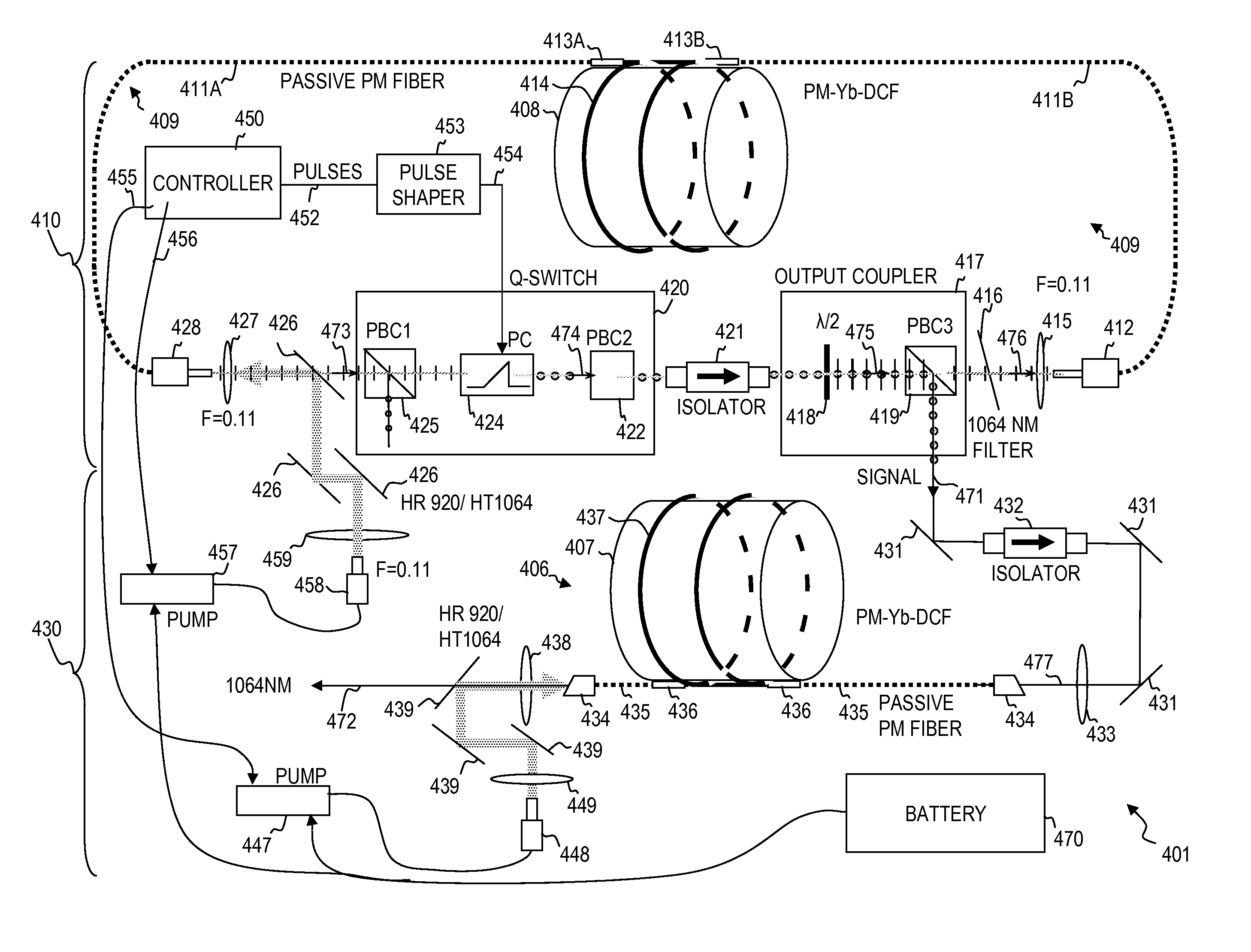
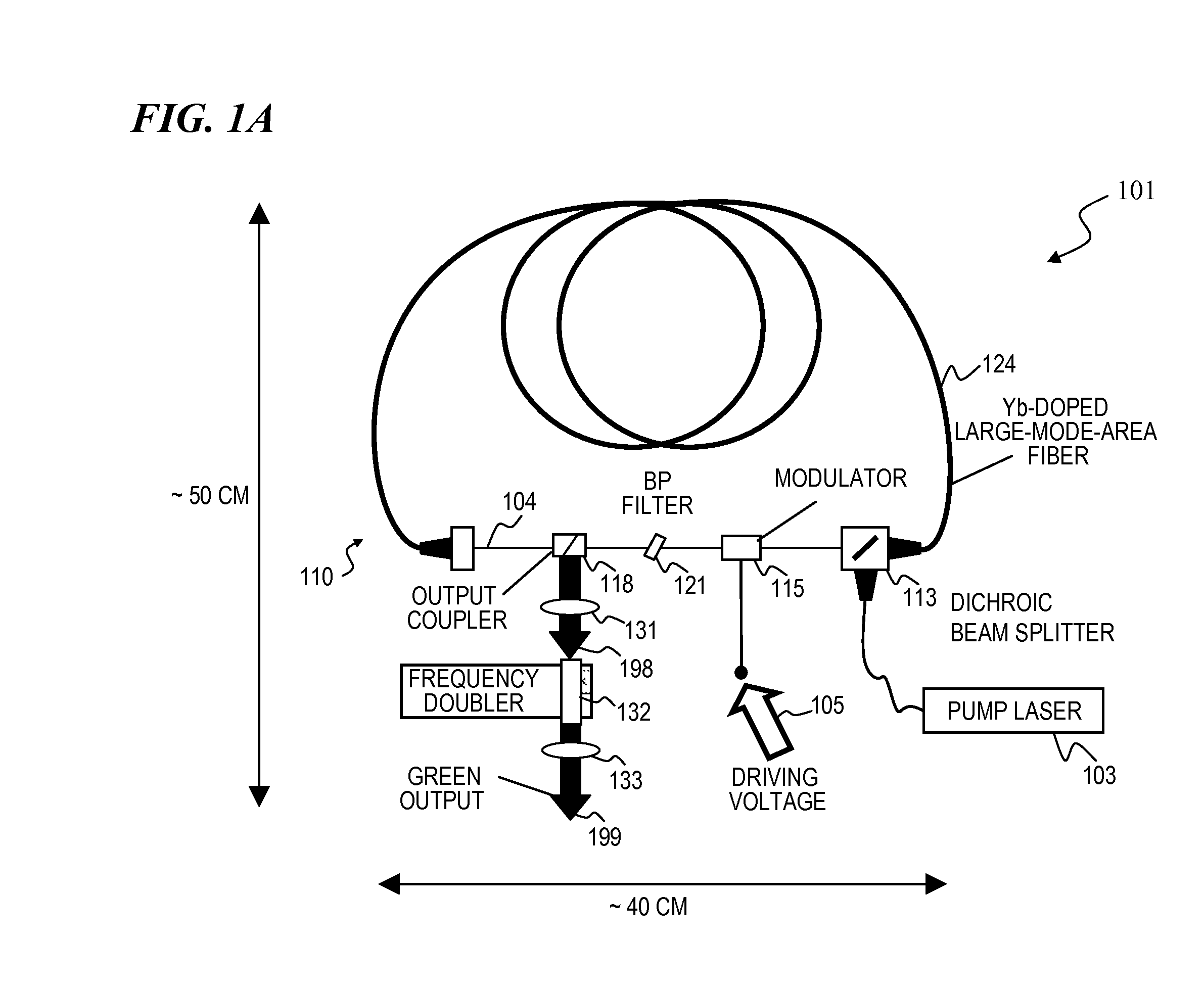
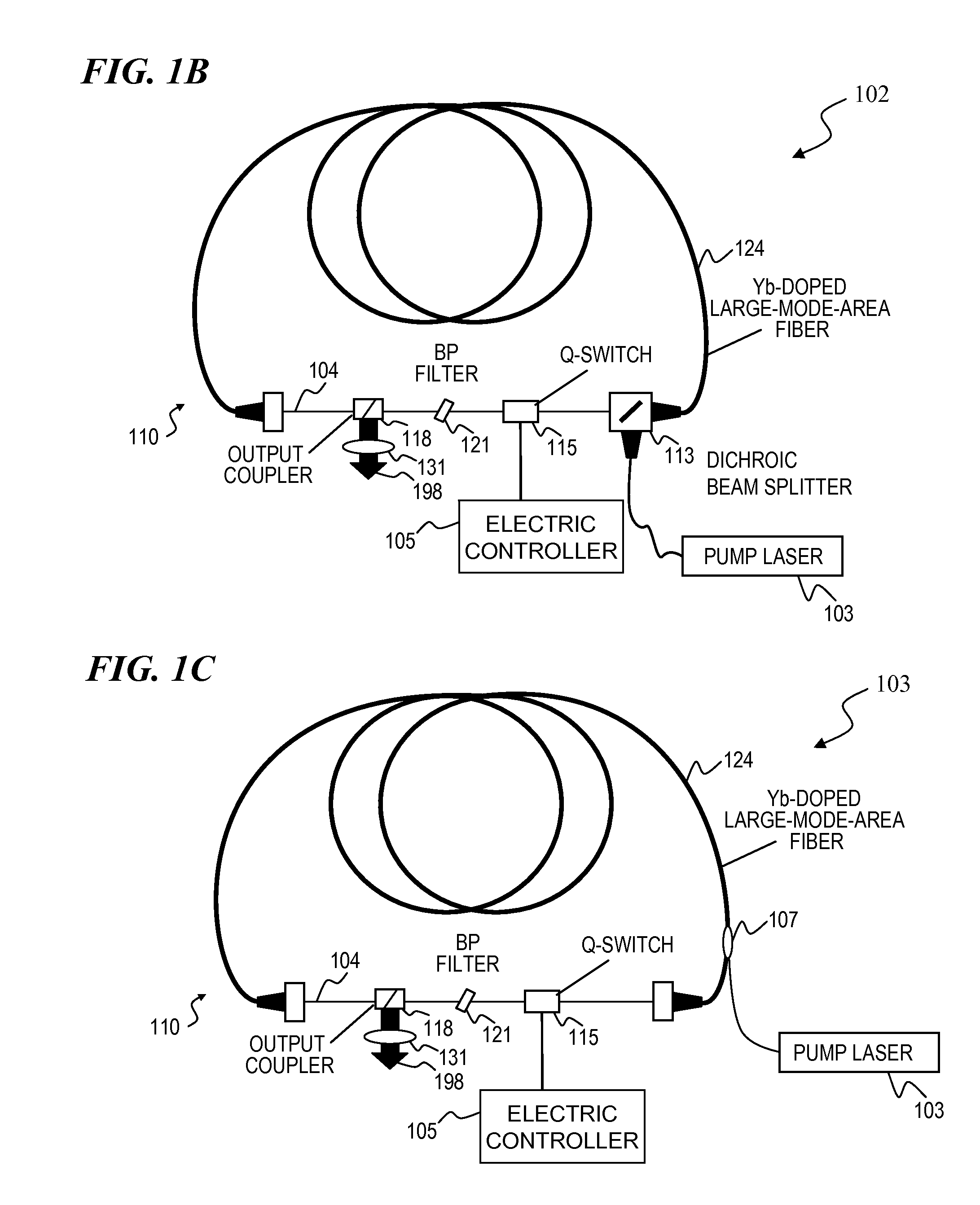
The present invention is a laser system that can produce high-power output pulses with low pulse-to-pulse amplitude / temporal instabilities and feedback effects. It consists of a unidirectional ring cavity, which reduces these instabilities. In a specific embodiment, the laser includes a rare-earth-doped fiber with low core NA for minimizing spontaneous emission, an electro-optic switch for reducing circulation and amplification of spontaneous emission, an output coupler, and an intracavity band-pass filter to enforce lasing operation in narrow wavelength range. This laser system can be used for cutting, ablation, and cauterization of soft tissue, and has advantages of low cost, compact footprint, and simple setup and operation.

Problems solved by technology

The current state-of-the-art lasers for outputting high-power green light are very costly.
Similarly, very high-power pulsed infrared (IR) lasers can be quite costly, making impractical their use with low-cost frequency-conversion optical devices.
This leads to decreased losses of guided desired light as well as to decreased losses through emission of undesired light, compared to devices of the prior art.

Method used


Image

  • Method and apparatus for high-power, pulsed ring fiber oscillator
  • Method and apparatus for high-power, pulsed ring fiber oscillator
  • Method and apparatus for high-power, pulsed ring fiber oscillator

Examples


Embodiment Construction

[0052]Although the following detailed description contains many specifics for the purpose of illustration, a person of ordinary skill in the art will appreciate that many variations and alterations to the following details are within the scope of the invention. Accordingly, the following preferred embodiments of the invention are set forth without any loss of generality to, and without imposing limitations upon the claimed invention. Further, in the following detailed description of the preferred embodiments, reference is made to the accompanying drawings that form a part hereof, and in which are shown by way of illustration specific embodiments in which the invention may be practiced. It is understood that other embodiments may be utilized and structural changes may be made without departing from the scope of the present invention.

[0053]The leading digit(s) of reference numbers appearing in the Figures generally corresponds to the Figure number in which that component is first intr...


PUM


Abstract

A ring laser includes a large-core rare-earth-doped fiber ring-connected with a free-space path having an electro-optic switch, output coupler, and intracavity band-pass filter to enforce lasing operation in narrow wavelength range. In some cavity-dumped modes, the laser is configured in a similar manner, except that an output coupler is omitted since the optical power is extracted from the laser cavity by the electro-optic switch itself. The same laser can be configured to operate in Q-switched and / or cavity-dumping modes as well as in hybrid modes (e.g., partial Q-switch, followed by cavity dumping, or even CW). In some embodiments, the laser can be used as, or inject laser light into, a regenerative solid-state amplifier, or a Raman laser, or can be also used to generate visible, ultra-violet, mid-infrared, and far-infrared (THz) radiation via nonlinear wavelength conversion processes. The various embodiments can use a power oscillator or seed-plus-amplifier MOPA configuration.

Description

CROSS-REFERENCE TO RELATED APPLICATIONS[0001]This is a divisional of and claims benefit of U.S. patent application Ser. No. 12 / 053,551 filed Mar. 21, 2008, titled “HIGH-POWER, PULSED RING FIBER OSCILLATOR AND METHOD” (which issued as U.S. Pat. No. 7,876,803 on Jan. 25, 2011), which claims priority to U.S. Provisional Patent Application 60 / 896,265 filed on Mar. 21, 2007, titled “HIGH-POWER, PULSED RING FIBER OSCILLATOR,” each of which is incorporated herein by reference in its entirety.[0002]This invention is related to U.S. patent application Ser. No. 11 / 257,793 filed Oct. 24, 2005 and titled “APPARATUS AND METHOD FOR OPTICAL STIMULATION OF NERVES AND OTHER ANIMAL TISSUE” (now U.S. Pat. No. 7,736,382, issued Jun. 15, 2010 to James S. Webb et al.);[0003]U.S. patent application Ser. No. 11 / 536,639 filed Sep. 28, 2006 and titled “MINIATURE APPARATUS AND METHOD FOR OPTICAL STIMULATION OF NERVES AND OTHER ANIMAL TISSUE” (now U.S. Pat. No. 7,988,688, issued on Aug. 2, 2011);[0004]U.S. Pro...

Claims


Application Information

Patent Timeline
Patent Type & Authority Patents(United States)
IPC IPC(8): H01S3/30
CPCH01S3/09408H01S3/1618H01S3/1103H01S3/0057H01S3/115H01S3/06712H01S3/06708H01S3/0092H01S3/06791H01S3/2308G02F1/37H01S3/094011H01S3/08027
Inventor DI TEODORO, FABIOVATTER, TRACY W.BROOKS, CHRISTOPHER D.ROYSE, JR., ROBERT W.SAVAGE-LEUCHS, MATTHIAS P.
Owner LOCKHEED MARTIN ACULIGHT CORP
Learn More