
Single Motor Power and Communication Cable

Active Publication Date: 2014-04-10
ROCKWELL AUTOMATION TECH
View PDF13 Cites 31 Cited by
  • Summary
  • Abstract
  • Description
  • Claims
  • Application Information

AI Technical Summary

Benefits of technology

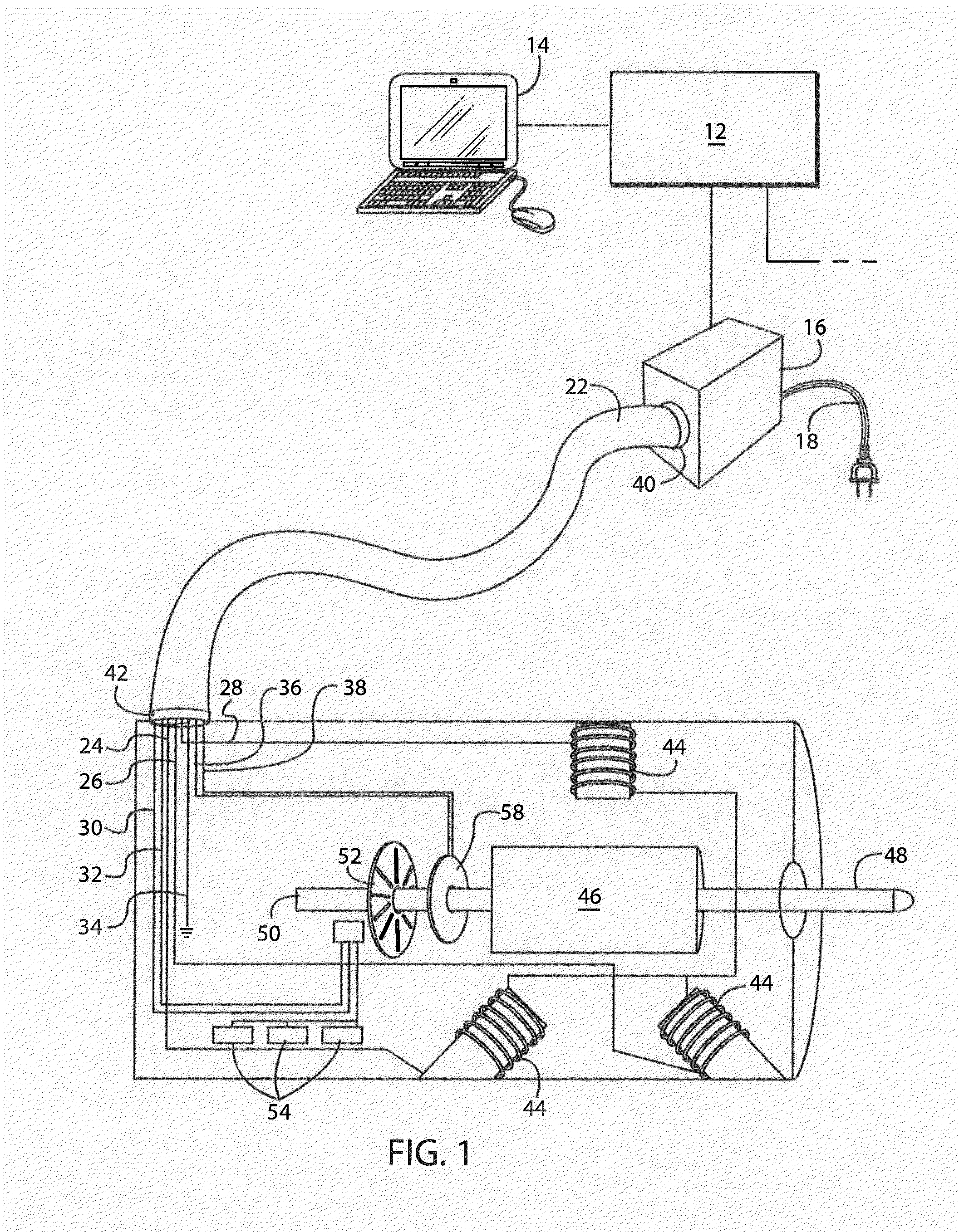
The present invention combines power delivery and communication in a single cable to save cost and complexity, while reducing noise and interference. By grouping power conductors together and electrically shielding them, noise from high voltage power conductors is minimized. Communications conductors are also grouped and shielded to minimize interference. The use of insulating and filler materials with low dielectric constants further improves signal integrity and system durability. These constructions allow for simultaneous delivery of high voltage power and low voltage data communication over the same cable, while minimizing the drawbacks of previous attempts.

Problems solved by technology

Delivery of such power to the motor typically requires transmission of significant amounts of power and energy, which is inherently a source of electrical interference and noise.
All such communication transmission lines typically involve low voltage electrical signals that are susceptible to electrical interference and noise, which may thereby cause signal integrity loss and resulting data loss.
Current implementations requiring multiple cables for separate power delivery and communications thereby increasing the cost and complexity of the designs by automatically doubling the number of cables and connectors that are required.
On the other hand, recent attempts toward combining power and communication conductors in a single cable continue to suffer from electrical noise and interference drawbacks on the data communication lines as described above, thereby limiting their possible range of transmission line lengths, data communication speeds and system reliability.

Method used


Image

  • Single Motor Power and Communication Cable
  • Single Motor Power and Communication Cable
  • Single Motor Power and Communication Cable

Examples


Embodiment Construction

[0023]One or more specific embodiments of the present invention will be described below. It is specifically intended that the present invention not be limited to the embodiments and illustrations contained herein, but include modified forms of those embodiments including portions of the embodiments and combinations of elements of different embodiments as come within the scope of the following claims. It should be appreciated that in the development of any such actual implementation, as in any engineering or design project, numerous implementation-specific decisions must be made to achieve the developers' specific goals, such as compliance with system-related and business related constraints, which may vary from one implementation to another. Moreover, it should be appreciated that such a development effort might be complex and time consuming, but would nevertheless be a routine undertaking of design, fabrication, and manufacture for those of ordinary skill having the benefit of this...


PUM


Abstract

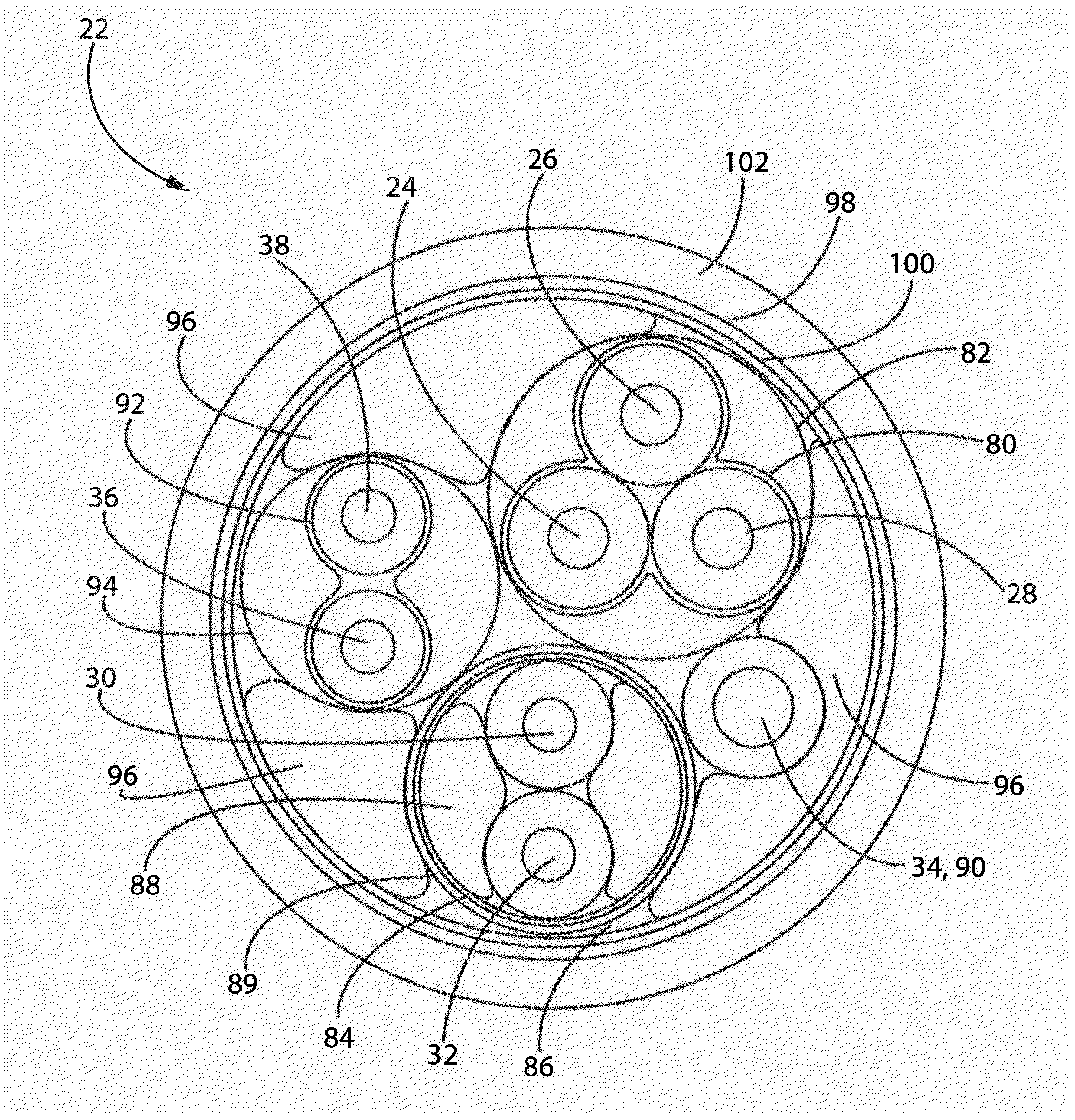
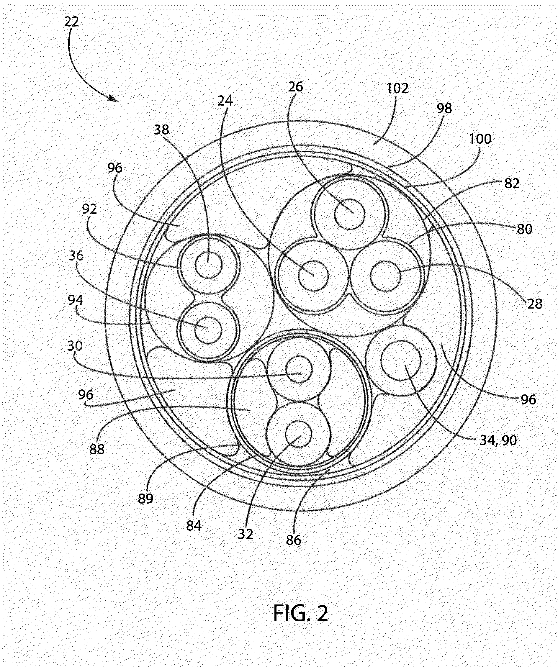
Aspects of the present invention provide a combined power and communications cable for use with a motor and drive unit in an industrial control system. By grouping, electrically shielding and jacketing particular conductors, and applying certain fillers, noise and interference onto low voltage communication conductors caused by high voltage power conductors is minimized. The cable may comprise first, second and third insulated conductors twisted together and covered by a cable jacket (first group); fourth and fifth insulated conductors twisted together and covered by an electrical shield (second group); and a sixth insulated conductor for delivering a protective ground (third group). The first, second and third groups are twisted together, covered by an electrical shield and covered by a cable jacket. Filler may be formed around the fourth and fifth insulated conductors, and may be formed around the first, second and third groups, to substantially maintain round geometric shapes.

Description

BACKGROUND OF THE INVENTION[0001]The present invention relates to industrial control systems and, in particular, to power and communications cabling for use with a motor and a drive unit in an industrial control system.[0002]Industrial controllers are specialized computer systems used for the control of industrial processes or machinery, for example, in a factory environment. Industrial controllers typically control numerous modules via specialized control networks for accomplishing different tasks in the industrial system. One such module may be a variable frequency drive (“VFD”) unit, which, in turn, may deliver power to, communicate with and control a motor. In industrial applications, motors may be used to affect a variety of motions in the industrial process. For example, motors may be operated at continuous or variable speeds, such as for turning the blades of a fan or the rollers of an assembly line at constant or variable speeds at different times, or may be used to precisel...

Claims


Application Information

Patent Timeline
IPC IPC(8): H01B11/06H01B13/00H01B9/04
CPCH01B7/04H01B7/1895H01B13/02
Inventor SIDLYAREVICH, TIMOTHY P.
Owner ROCKWELL AUTOMATION TECH
Learn More