
Road structure detection and tracking

a technology for detecting and tracking roads, applied in the field of road structure identification, can solve the problems of reducing the chances or false alarms of incorrectly identifying clear paths, and accelerating the overall processing time, so as to reduce the chances or false alarms, and accelerate the overall processing time

Active Publication Date: 2014-06-10
GM GLOBAL TECH OPERATIONS LLC
View PDF6 Cites 30 Cited by
  • Summary
  • Abstract
  • Description
  • Claims
  • Application Information

AI Technical Summary

Benefits of technology

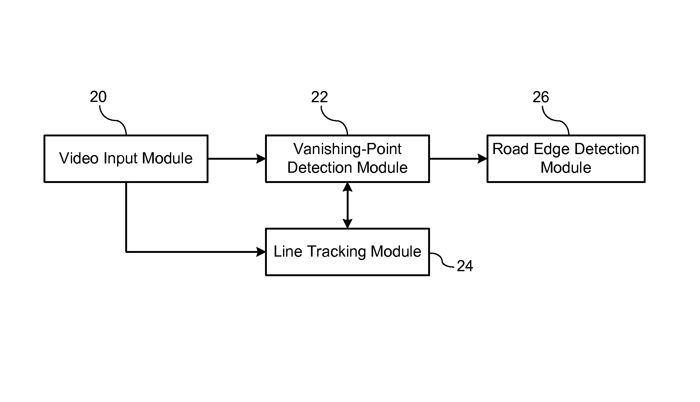
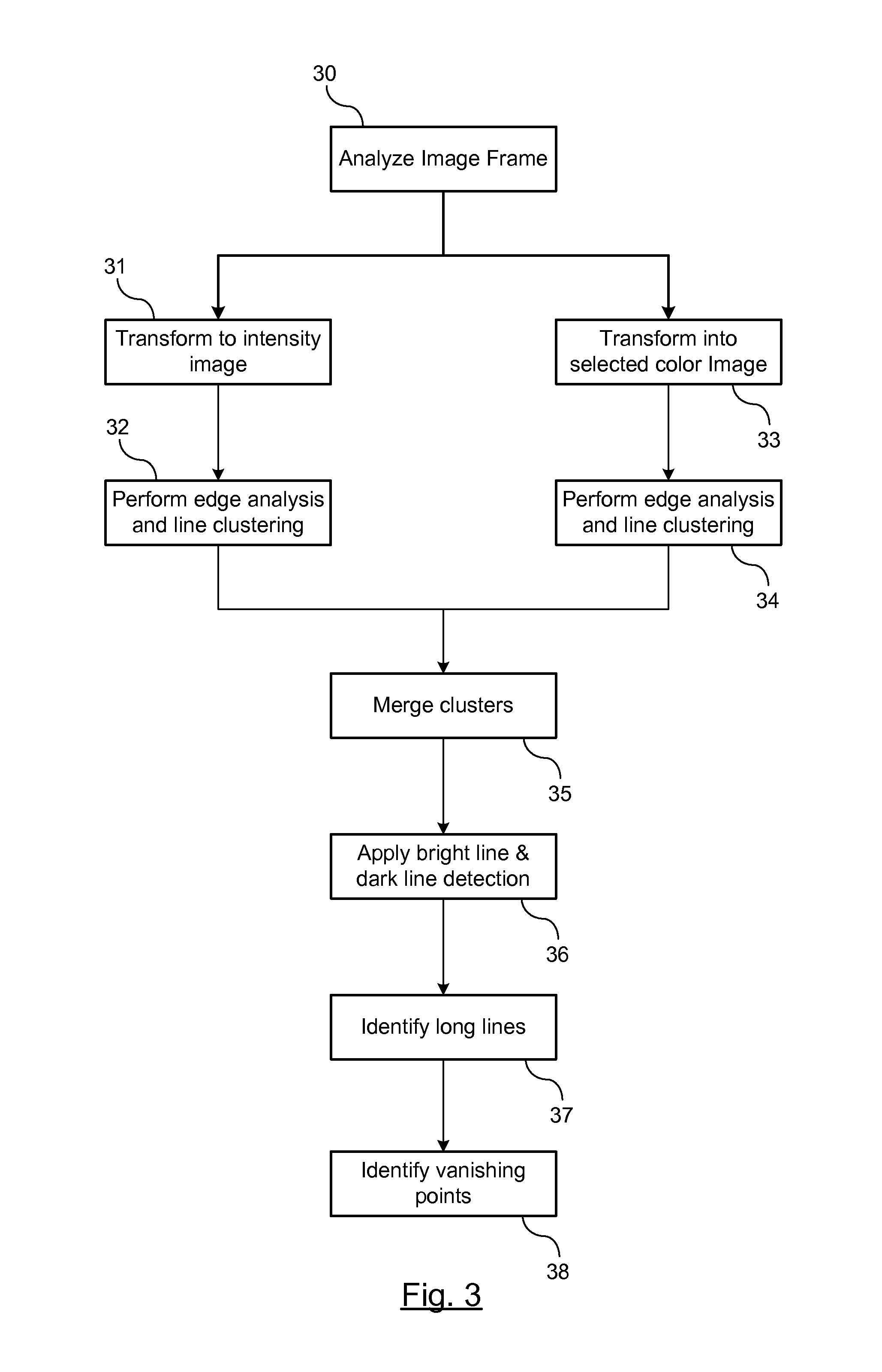
The patent text describes a method for identifying a road structure within a captured image and using it to detect clear paths. This helps improve the overall processing time and reduces the likelihood of false alarms. The method involves generating an illumination intensity image and a yellow image for line clusters within the image. These line clusters are then merged and potential line candidate detection is performed. A vanishing point in the image is also identified and line tracking and vanishing point tracking is performed to improve the identification of the vanishing point and potential line candidates. These line candidates are then provided to a classifier to identify whether the line candidate is a road edge. The identified road edges are then utilized to define a boundary of the road for assisting clear path detection.

Problems solved by technology

Identifying a targeted region within the image not only accelerates the overall processing time for detecting the clear path, but it reduces the chances or false alarms of incorrectly identifying clear path.

Method used


Image

  • Road structure detection and tracking
  • Road structure detection and tracking
  • Road structure detection and tracking

Examples


Embodiment Construction

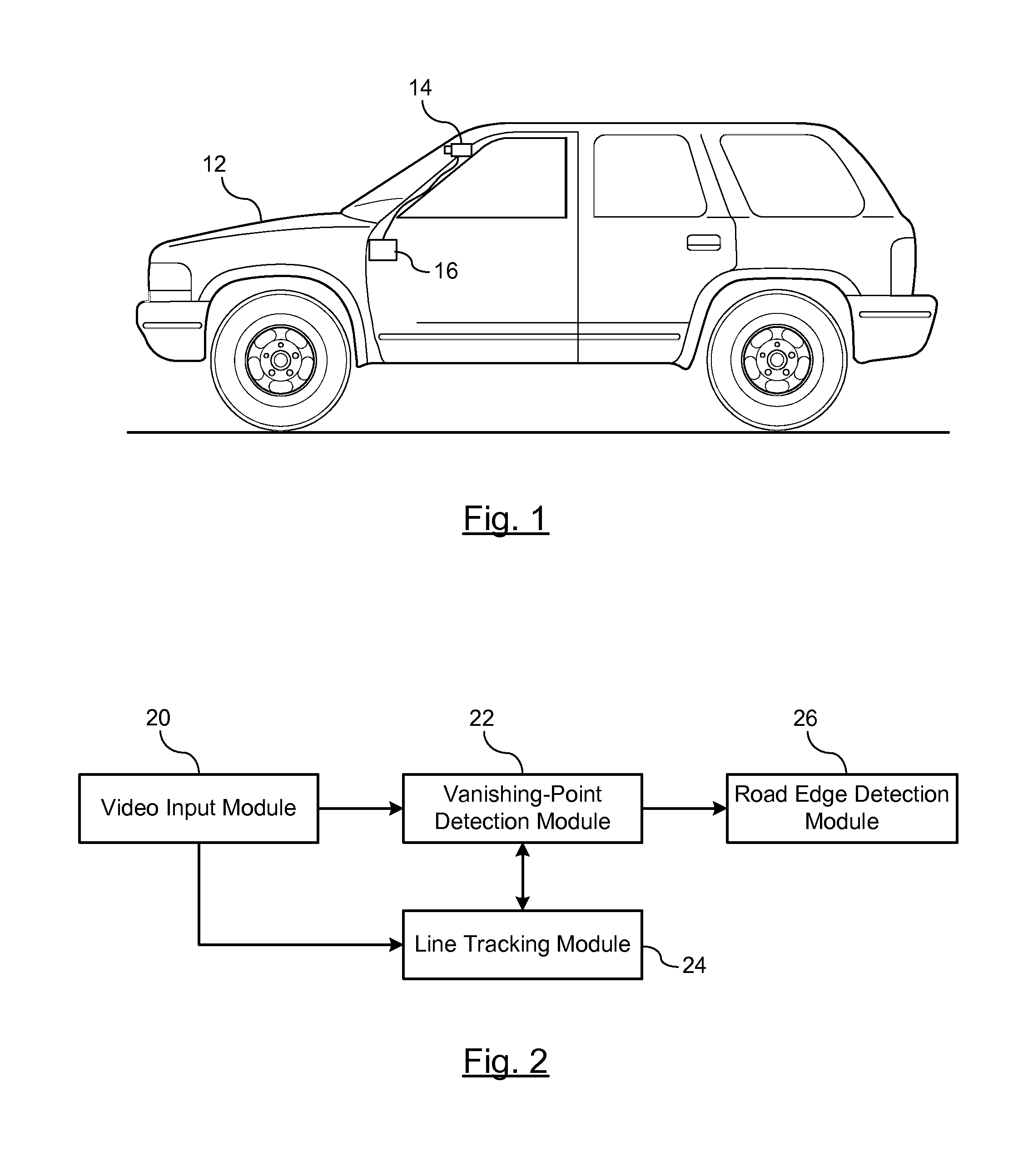
[0012]There is shown in FIG. 1 a vehicle 12 integrating a road edge detection system for identifying a clear path of travel. The road edge detection system includes an image capture device 14 mounted to the vehicle 12. The image capture device 14 is in communication with a processing unit 16.

[0013]The image capture device 14 may include a camera or other imaging device that captures images of the road of travel. The image capture device 14 captures images forward of the vehicle that are used to identify a clear path of travel. Preferably, the image capture device 14 is configured for performing continuous image capture. The images captured by the image capture device 14 may be stored in a memory of the image capture device 14, transferred to an off-board memory device, or may be transferred to the processing unit 16 for analysis. Moreover, more than one image capture device may be used in order to capture images rearward and / or on both sides of the vehicle for clear path detection. ...


PUM


Abstract

Method for detecting road edges in a road of travel for clear path detection. Input images are captured at various time step frames. An illumination intensity image and a yellow image are generated from the captured image. Edge analysis is performed. The line candidates identified in a next frame are tracked. A vanishing point is estimated in the next frame based on the tracked line candidates. Respective line candidates are selected in the next frame. A region of interest is identified in the captured image for each line candidate. Features relating to the line candidate are extracted from the region of interest and input to a classifier. The classifier assigns a confidence value to the line candidate identifying a probability of whether the line candidate is a road edge. The potential line candidate is identified as a reliable road edge if the confidence value is greater than a predetermined value.

Description

BACKGROUND OF INVENTION[0001]An embodiment relates generally to identifying road structure for detecting clear path of travel.[0002]Vision-imaging systems are used in vehicles for enhancing applications within the vehicle such as autonomous driving system or semi-autonomous driving systems. Such systems may be used to autonomously or semi-autonomously control the vehicle through steering systems, throttle control, braking control, or even utilized for lane departure warning systems.[0003]Clear path detection systems identify a clear path in which to operate a vehicle traveling along a road. The path of travel is sensed for objects, including all non-road surfaces, so that the vehicle may travel along an uninterrupted path of travel. Features within an image may be detected and analyzed according to their form and relationship to the roadway. However, such methods may be slow due to intense data processing or the inability to distinguish clear path features and non-clear path feature...

Claims


Application Information

Patent Timeline
Patent Type & Authority Patents(United States)
IPC IPC(8): H04N7/18G06K9/00
CPCB60W40/072G06T2207/20136G06T7/0083G06T2207/20081G06K9/4638G06T2207/20084G06T2207/30256G06T2207/10024B60W40/04G06K2009/3291G06T2207/10016G06K9/00798G06T7/12G06T7/181G06V20/588G06V10/62G06V10/457
Inventor ZHANG, WENDEWANG, JINSONG
Owner GM GLOBAL TECH OPERATIONS LLC
Learn More