
Shift controlling apparatus for vehicle

a technology of shifting control and vehicle, which is applied in mechanical devices, instruments, transportation and packaging, etc., can solve the problems of increased cost and unfavorable known techniques, and achieve the effects of reducing speed, convenient use and easy driving

Active Publication Date: 2014-06-10
HONDA MOTOR CO LTD
View PDF16 Cites 7 Cited by
  • Summary
  • Abstract
  • Description
  • Claims
  • Application Information

AI Technical Summary

Benefits of technology

The invention provides a drive mode shift map that can shift between a sport mode and a first mode to achieve a wide range of running states. The shift map automatically changes over to the sport mode when a driver selects it, making the driving easier and more convenient. The mode change is made based on different driving scenarios such as cornering or riding on an uphill road. The driver can also manually select the sport mode if they need to, providing more flexibility and enjoyment during different driving situations. Additionally, the invention allows for a smooth transition between the sport mode and the first mode when the driver is not actively using the sport mode, preventing unnecessary mode changes. Overall, the invention improves the driving experience and allows for better handling of different driving scenarios.

Problems solved by technology

However, in such a case that the vehicle continuously runs in the “1” range or the “2” range or in a like case, the known technique is not very advantageous if the fuel cost, engine noise and so forth are taken into consideration.
Further, since a sensor for detecting the gradient is required, the cost increases.

Method used


Image

  • Shift controlling apparatus for vehicle
  • Shift controlling apparatus for vehicle
  • Shift controlling apparatus for vehicle

Examples


Embodiment Construction

[0030]A shift controlling apparatus according to the present invention is described in detail below in connection with a present exemplary embodiment with reference to the accompanying drawings.

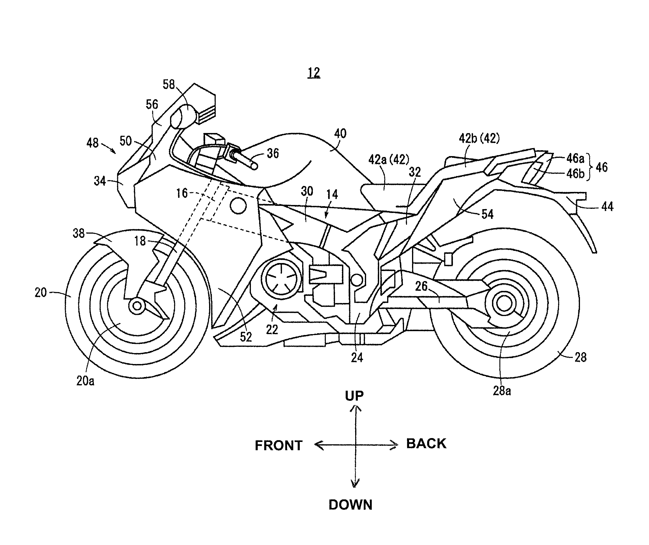
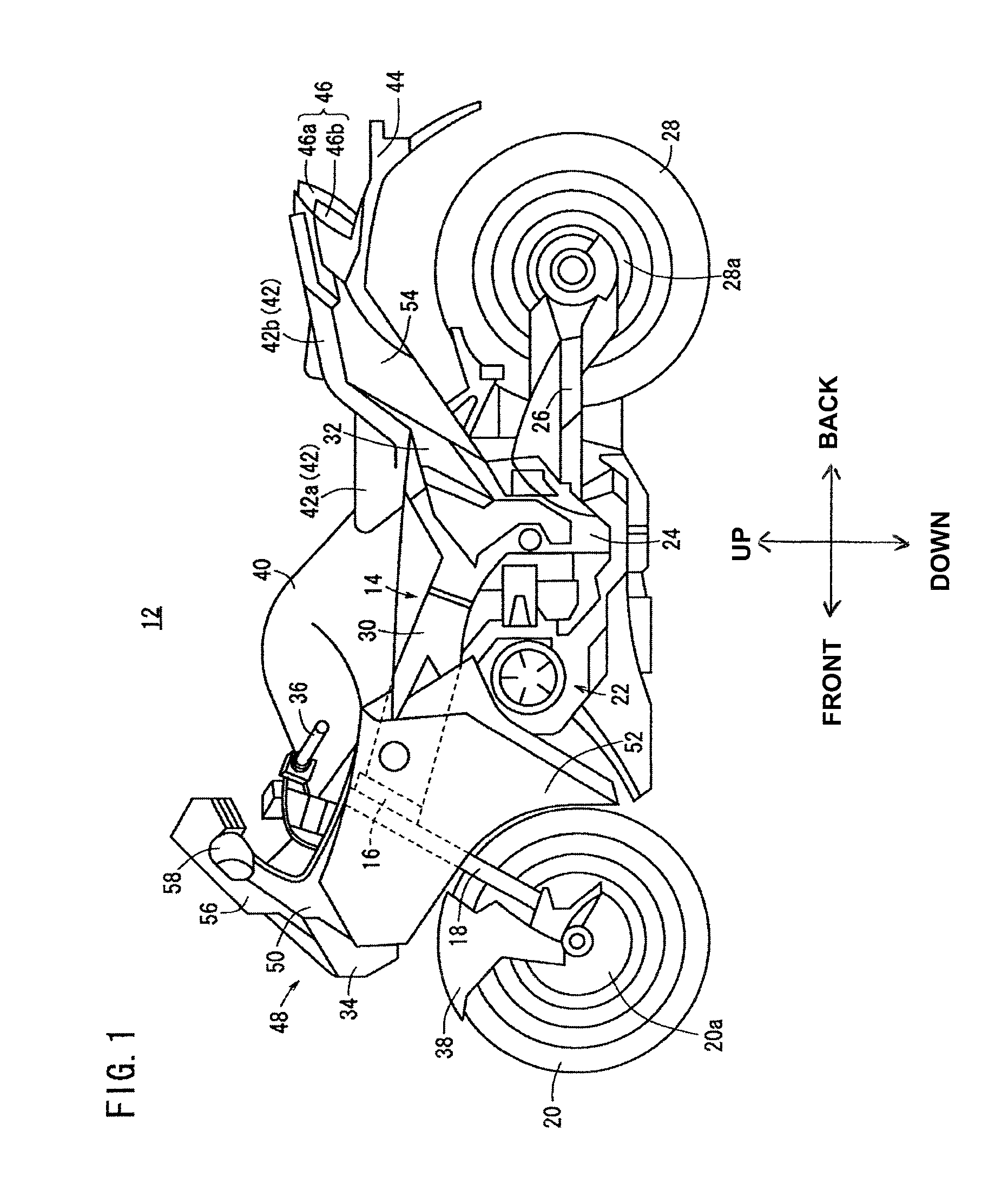
[0031]FIG. 1 is a left side elevational view of a motorcycle (including a bicycle with a prime mover) 12 in which a shift controlling apparatus according to an exemplary embodiment of the present invention is incorporated. It is to be noted that, in order to facilitate understanding of the invention, unless otherwise specified, the forward and backward directions and the upward and downward directions are described with reference to the direction indicated by an arrow mark in FIG. 1 and the leftward and rightward directions are described with reference to a direction as viewed from a driver seated on a vehicle body.

[0032]The motorcycle (vehicle) 12 includes a vehicle body frame 14 which configures a vehicle body, a pair of left and right front forks 18 rotatively supported on a head pipe 16 p...


PUM


Abstract

Shift controlling apparatus for a vehicle which automatically carries out changeover between a plurality of shift gear stages based on an automatic shift map including a drive mode shift map and a sport mode shift map having an increased region in which a speed change ratio is low compared to the drive mode shift map and corresponds to more sporty operation than that of the drive mode shift map. The drive mode shift map has a first mode portion and a second mode portion having an increased region in which the change gear ratio is low compared to the first mode portion, but smaller than the increased region of the sport mode shift map. Changeover between the first and second mode portions is carried out based on an acceleration history in accordance with a throttle opening of the vehicle.

Description

TECHNICAL FIELD[0001]This invention relates to a shift controlling apparatus, and more particularly to such an apparatus for a vehicle such as a motorcycle.BACKGROUND ART[0002]Japanese Patent Laid-Open No. Hei 8-210487 discloses a technique wherein different shift maps are provided for one range and are selectively used in response to a running state. For example, a technique is disclosed wherein, where a shift lever is fixed to the “1” range, the gradient during running is decided, and on a downhill, a downhill map is automatically selected to permit shift down, but on an uphill or a flat other than a downhill, an uphill map or a flat road map is automatically selected to permit shift up without the necessity for operating the shift lever to the “D” range.[0003]The known technique is specialized to a case of shift at the “1” range and the “2” range and is particularly effective where the vehicle runs on a road along which an uphill and a downhill repetitively appear. However, in su...

Claims


Application Information

Patent Timeline
Patent Type & Authority Patents(United States)
IPC IPC(8): G06F7/00
CPCF16H59/36G06F17/00F16H59/18F16H61/0213F16H2061/0227F16H59/48
Inventor TAKEUCHI, YOSHIAKIYOKOGAWA, YUKIOKITTAKA, EIJI
Owner HONDA MOTOR CO LTD
Learn More