Twin bladed scraper tool

a scraper tool and twin blade technology, applied in the direction of cleaning processes, vehicles, applications, etc., can solve the problems of ineffective hand grip, inability to exert pressure, and ineffective blade configuration of the scraper, so as to reduce fatigue, reduce hand and wrist stress, and save effort

Inactive Publication Date: 2014-06-24
ROLPH IAN DOUGLAS
View PDF10 Cites 2 Cited by
  • Summary
  • Abstract
  • Description
  • Claims
  • Application Information

AI Technical Summary

Benefits of technology

[0006]An advantage of the invention is that it reduces stress in the users hand and wrist to reduce fatigue.
[0007]Another advantage of the invention is that it permits the user to direct nearly all energy to the scraping action rather than wasting effort in maintaining stability of the device.
[0008]In accordance with the invention a robust one piece twin bladed scraper tool for scraping material from a surface comprises of a pair of opposing identical blades under a cylindrical in line handle, wherein the blades are arranged to form an open bottomed triangle with the blades diverging away from each other at an angle of less than 90 degrees.
[0009]The blades preferably diverge away from each other at an angle of greater than 60 degrees, creating a blade to surface angle of contact greater than 45 degrees but less than 60 degrees.
[0010]The blade and handle length may be more than two times the blades distance apart, at the point of contact with the surface to be scraped.
[0011]The handle may incorporate rubber ribs on its exterior surface as an aid to gripping.

Problems solved by technology

The manual grip commonly used to grasp most scrapers is inefficient and does not allow the user to exert the pressure required to remove stubborn deposits from motor vehicle windscreens while simultaneously maintaining the scrapper at the correct angle to allow the blade to work efficiently.
The result of this is usually having the scraper skid across the surface of the deposit or having to resort to two handed use for which the above mentioned scrapers are not designed.
However blade configurations on these devices do not lend themselves to effective removal of stubborn deposits either by having a single blade which encompasses the device requiring many passes for the blade to initially penetrate the substrate, or as illustrated in '836 to Williams by having smaller blades a greater distance apart and an opposing handle which does not allow the required grip and arm alignment to apply maximum pressure to the device and its blades.
This results in more time and effort being expended to achieve the required clearance.

Method used


Image

  • Twin bladed scraper tool
  • Twin bladed scraper tool
  • Twin bladed scraper tool

Examples


Embodiment Construction

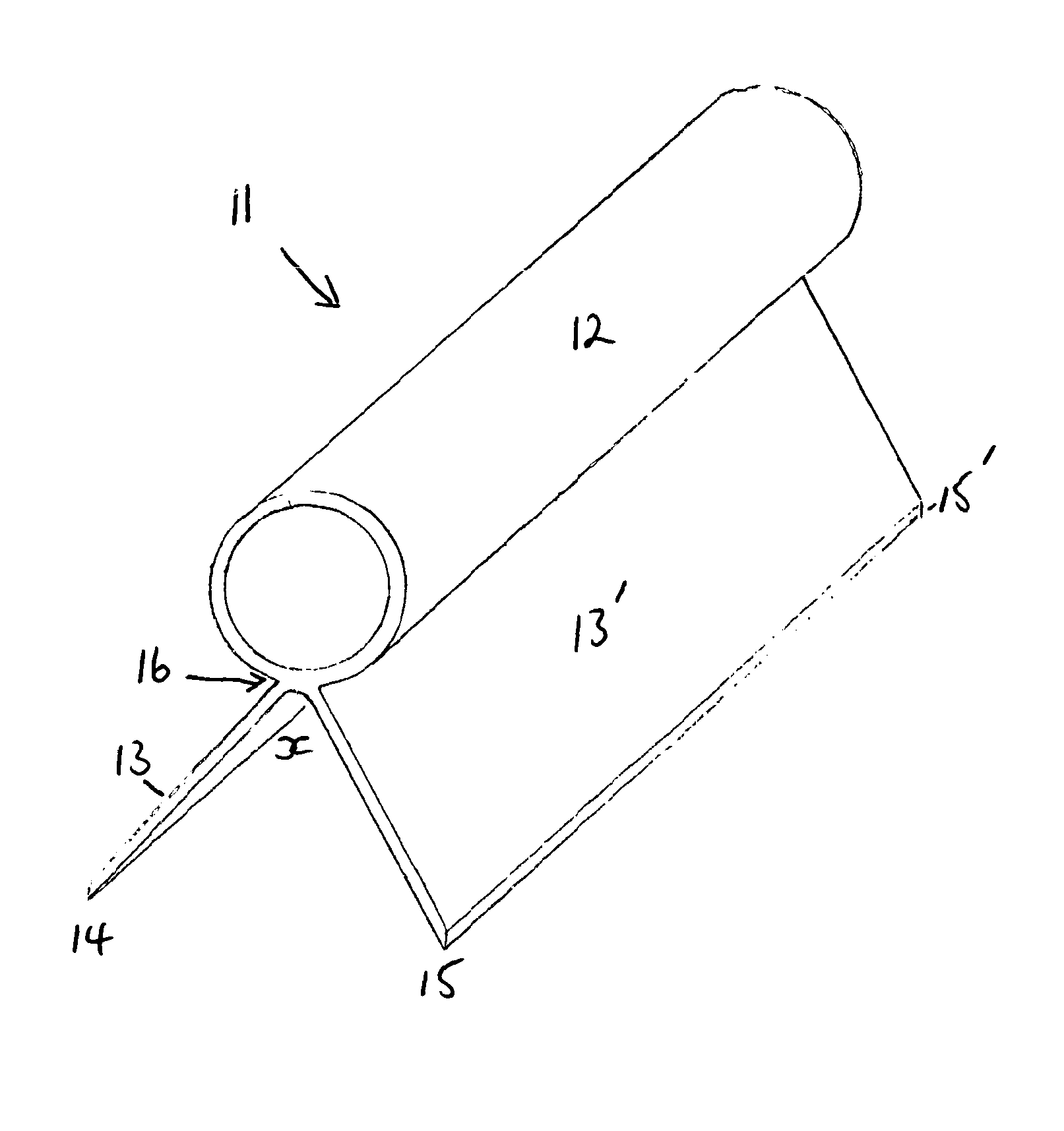
[0018]The invention relates to scrapers and more particularly to scrapers for removing ice and snow from vehicle windows and windscreens. The scraper apparatus according to present invention offers a more comfortable, efficient and reliable means of manually scraping ice and snow from a motor vehicle windscreen. While the invention is most suitable for scraping ice and snow from windows, it is appreciated that the apparatus may have beneficial use in almost any instance where it is required to scrape a surface to remove a substrate there from.

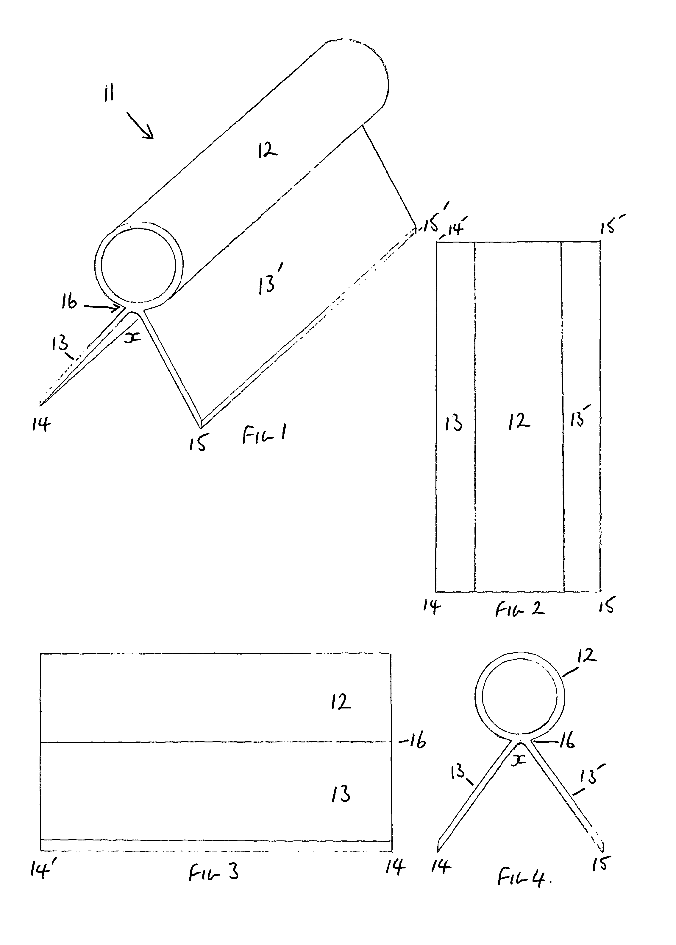
[0019]With reference to FIG. 1-4 the apparatus of the invention comprises of a pair of opposing blades 13,13′ diverging away from each other under a cylindrical handle 12 at an angle at x of between 60 and 90 degrees. The scraper 11 is fashioned from a durable plastic to give rigid blades in use but soft enough not to scratch glass. The scraper is likely to be extruded.

[0020]As best seen in FIGS. 1 and 4 the scraper 11, is fashioned in the shap...


PUM


Abstract

A scraper tool of a one piece construction is conformable for use in scraping various surfaces and is made up of a pair of scraper blades (13,13′) with their junction along the length of the tool, under its handle (12). The blades extend in opposite directions under the handle (12), in line with it, at a set angle forming an open bottom, with the handle (12) above the blades (13,13′) and the surface to be scraped. The application of force and direction of travel will allow the forward blade to “cut” substrates from a surface, the rear blade will maintain a cutting angle for the forward blade, the device will operate in a similar fashion on its reverse stroke.

Description

BACKGROUND AND FIELD OF THE INVENTION[0001]The invention relates to an apparatus for scraping substances from surfaces, and in particular to a novel and improved device for manually scraping ice, frost and snow from motor vehicle windscreens and windows. The invention is well suited for scraping frost build up from motor vehicle windscreens, but it is immediately appreciated that the invention finds beneficial use in nearly any application where it is desired to scrape a surface to remove a substance there from. Scraper devices typifying the present state of the art are disclosed in U.S. Pat. No. 4,275,476 to Hopkins et al., U.S. Pat. No. 3,130,436 to Krause, and U.S. Pat. No. 6,092,255 to Kim. The devices disclosed in the foregoing patents, and in the scrapers most frequently encountered in commercial use, generally consist of a handle section upon which is mounted a single scraping blade. The manual grip commonly used to grasp most scrapers is inefficient and does not allow the us...

Claims


Application Information

Patent Timeline
Patent Type & Authority Patents(United States)
IPC IPC(8): A47L13/02
CPCB60S3/045A47L1/16B08B1/00
Inventor ROLPH, IAN, DOUGLAS
Owner ROLPH IAN DOUGLAS
Why Eureka
Try Eureka