
Fuel vapor processors

a technology of fuel vapor and processor, which is applied in the direction of combustion air/fuel air treatment, electrical control, separation processes, etc., can solve the problems of inability to completely pass the supplied fuel vapor through the separation membrane, and the fuel-air ratio in the engine is not fixed, so as to achieve constant fuel-air ratio and avoid the increase of exhaust emissions

Active Publication Date: 2014-06-24
AISAN IND CO LTD
View PDF10 Cites 1 Cited by
  • Summary
  • Abstract
  • Description
  • Claims
  • Application Information

AI Technical Summary

Benefits of technology

The patent text describes a system for separating fuel vapor from the air in an engine. By controlling the volume of fuel vapor that enters the separator, the system can reduce the fuel vapor concentration in the air that enters the engine. This prevents the fuel vapor from being trapped in areas near the engine, which can cause emissions issues. Additionally, the system can control the fuel vapor concentration in the air that is released into the environment, to prevent air pollution. This results in a consistent fuel-air ratio for the engine, which can lower emissions levels in the exhaust.

Problems solved by technology

Therefore, when the very large amount of the fuel vapor is supplied to the separation membrane, it is difficult to pass the supplied fuel vapor through the separation membrane completely.
In such case, because the concentration of the fuel vapor in the diluted gas is not constant, fuel-air ratio in the engine is not fixed.

Method used


Image

  • Fuel vapor processors
  • Fuel vapor processors
  • Fuel vapor processors

Examples


Embodiment Construction

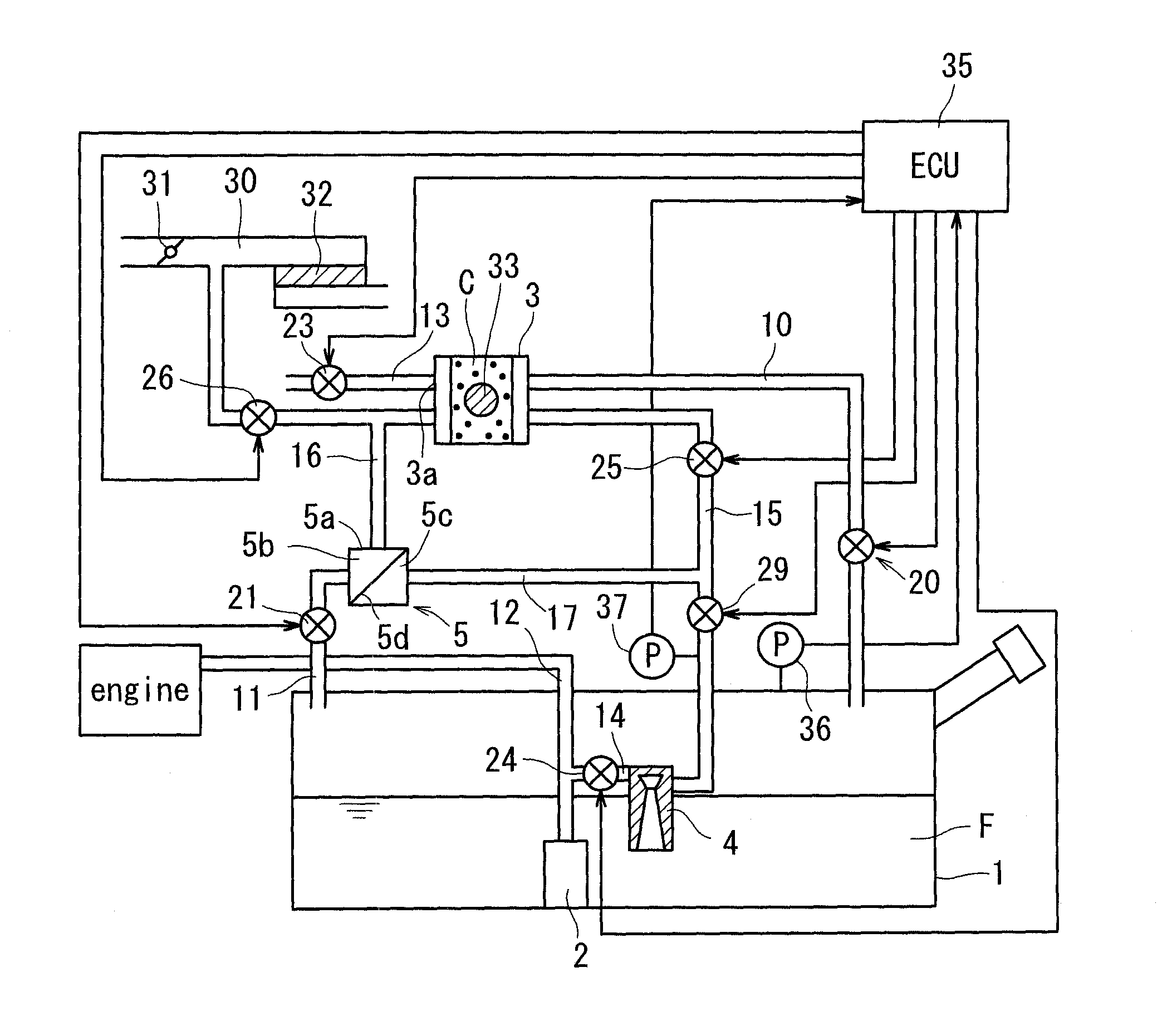
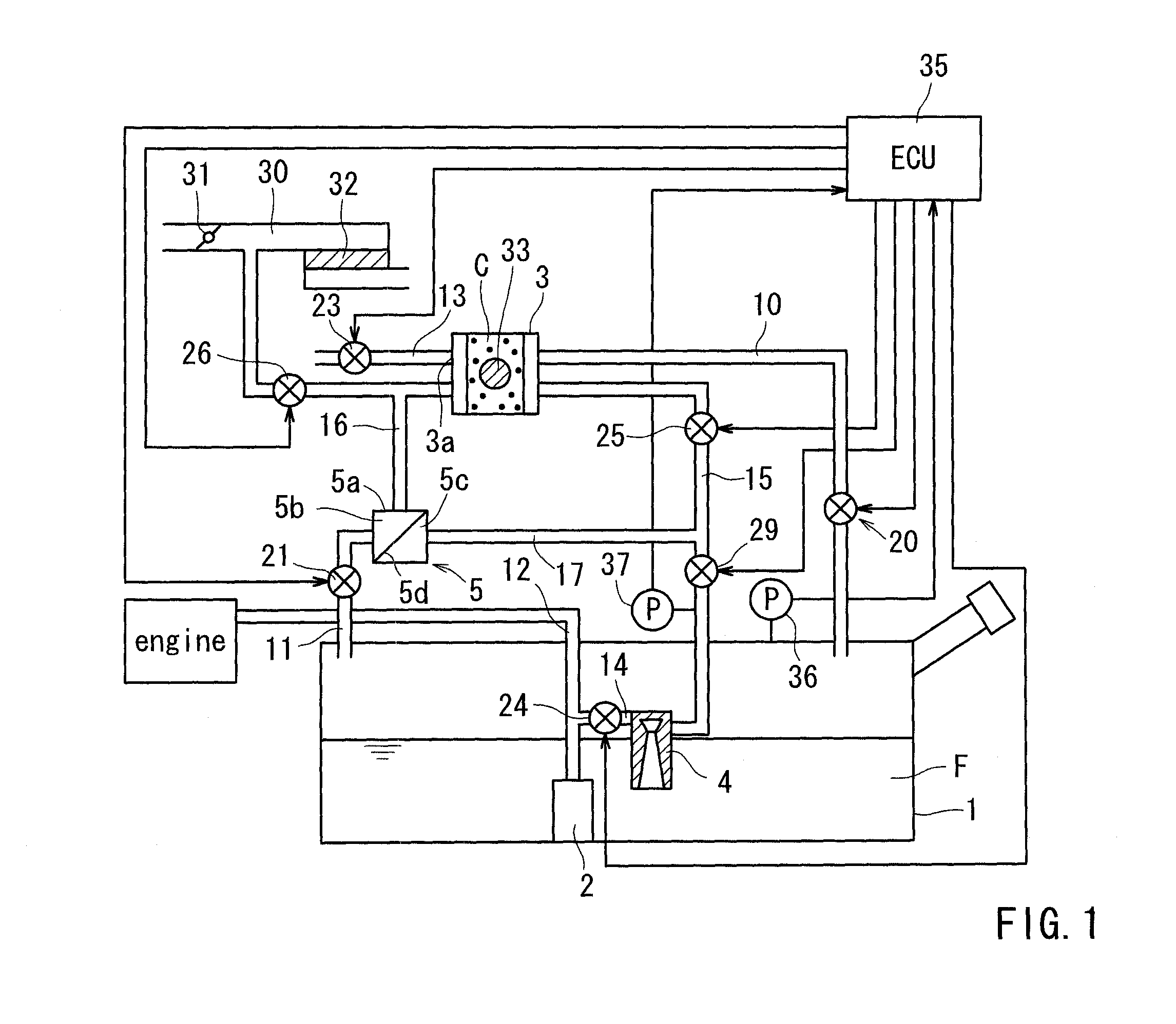
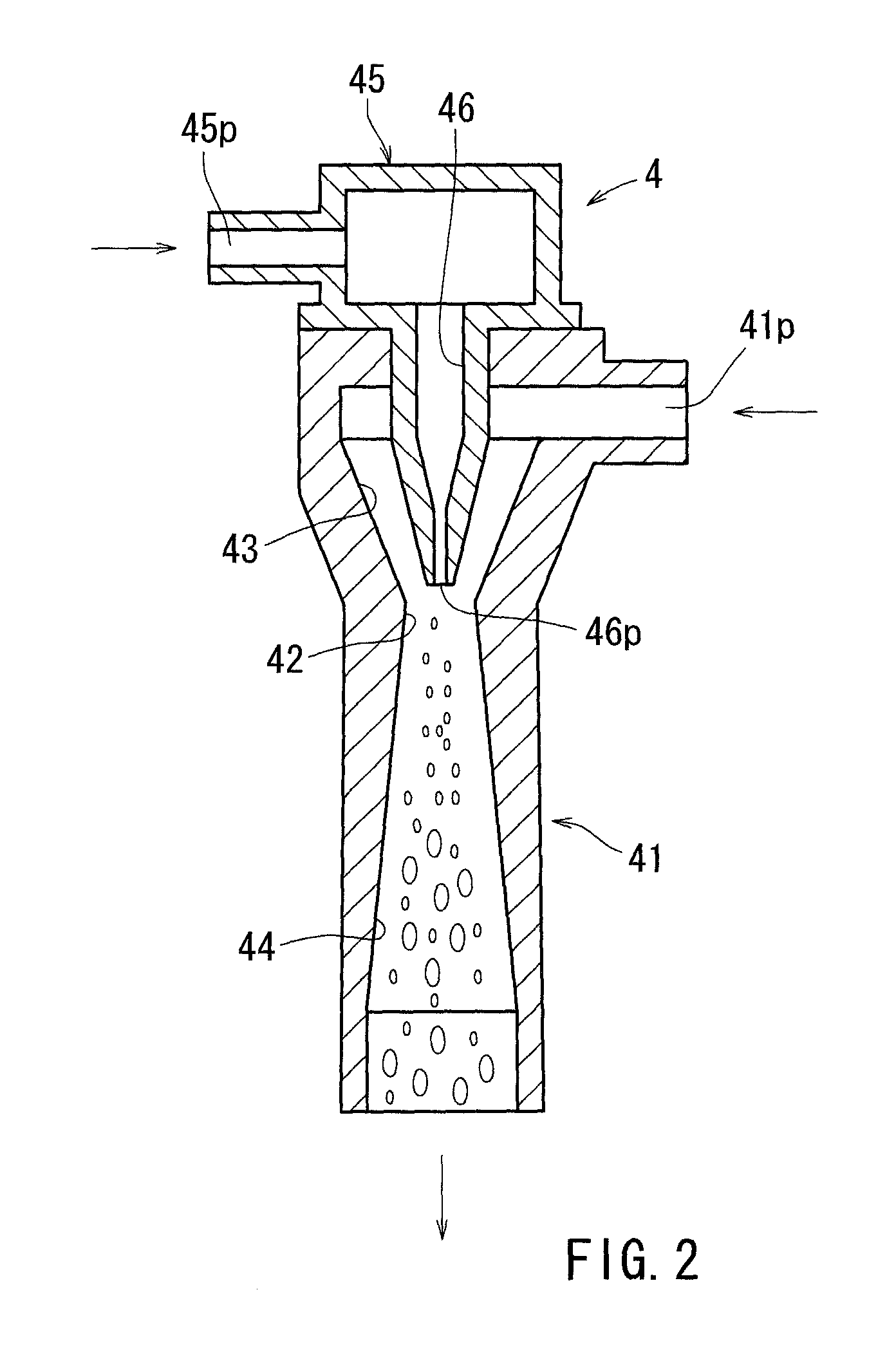
[0029]Each of the additional features and teachings disclosed above and below may be utilized separately or in conjunction with other features and teachings to provide improved fuel vapor processors. Representative examples of the present invention, which examples utilized many of these additional features and teachings both separately and in conjunction with one another, will now be described in detail with reference to the attached drawings. This detailed description is merely intended to teach a person of skilled in the art further details for practicing preferred aspects of the present teachings and is not intended to limit the scope of the invention. Only the claims define the scope of the claimed invention. Therefore, combinations of features and steps disclosed in the following detailed description may not be necessary to practice the invention in the broadest sense, and are instead taught merely to particularly describe representative examples of the invention. Moreover, var...


PUM

PropertyMeasurementUnit
pressureaaaaaaaaaa
pressureaaaaaaaaaa
internal pressureaaaaaaaaaa

Abstract

A fuel vapor processor has a fuel tank configured to reserve fuel, a canister containing adsorbent capable of adsorbing fuel vapor vaporized in the fuel tank, a separator receiving a fuel vapor containing gas from the fuel tank, a regulator controlling the volume of the fuel vapor containing gas supplied to the separator, and a suction unit capable of removing the fuel vapor from the canister. The separator selectively passes the fuel vapor therethrough in order to divide the fuel vapor containing gas into a first gas mainly containing the fuel vapor and a second gas having a fuel vapor density lower than the first gas. The suction unit suctions the first gas from the separator in order to return the first gas into the fuel tank. The second gas is introduced into the canister or is released into the atmosphere.

Description

[0001]This application claims priority to Japanese Patent Application Serial Numbers 2010-050211 and 2010-053047, the contents of which are incorporated herein by reference.BACKGROUND OF THE INVENTION[0002]1. Field of the Invention[0003]The present invention relates to fuel vapor processors, in particularly to fuel vapor processors mounted on a gas vehicle for preventing a large volume of fuel vapor from flowing into the atmosphere.[0004]2. Description of the Related Art[0005]A fuel vapor processor generally has a canister temporarily trapping fuel vapor vaporized in a fuel tank, a suction unit suctioning the fuel vapor from the canister, and a separator selectively passing the fuel vapor in a fuel vapor containing gas in order to concentrate the fuel vapor. The concentrated fuel vapor is returned into the fuel tank due to action of the suction unit.[0006]Japanese Laid-Open Patent Publication No. H11-93784 discloses a fuel vapor processor where fuel vapor vaporized in a fuel tank is...

Claims


Application Information

Patent Timeline
Patent Type & Authority Patents(United States)
IPC IPC(8): F02M33/08F02M33/02
CPCB01D50/00B01D53/02F02M33/04F02M25/089F02M25/0836F02M25/0854F02M25/0872F02D41/0032F02M25/08F02D41/0045B60K15/03504
Inventor MAKINO, KATSUHIKO
Owner AISAN IND CO LTD
Learn More