Removable cartridge cleaner

a cartridge cleaner and cleaning technology, applied in metal-working equipment, metal-working equipment, manufacturing tools, etc., can solve the problems of affecting timely maintenance activities, affecting the cleaning effect of belt cleaners, and unable to easily be manually removed

Active Publication Date: 2014-06-24
FLEXIBLE STEEL LACING
View PDF34 Cites 12 Cited by
  • Summary
  • Abstract
  • Description
  • Claims
  • Application Information

AI Technical Summary

Benefits of technology

[0010]In accordance with one aspect of the invention, a removable cartridge cleaner assembly is provided that allows for faster and easier removal of the belt cleaner blades out from under the conveyor belt. The present removable cartridge cleaner provides a tight engagement between the removable rail member and the elongate support assembly to minimize debris accumulation, as compared to prior cartridge cleaner assemblies which have a loose fit between the removable rail members and the support member, thereby providing spaces and / or gaps which allow debris and other material to collect therein. Such debris solidifies over time and effectively glues the removable channel member in place.
[0011]The present removable cartridge cleaner assembly includes an elongate rail or channel member and an elongate support assembly. Lower, free ends of legs of the channel member are configured to slide along an upper surface of the elongate support assembly. An opening of one of the channel member and support assembly includes a biasing surface configured to engage a securing portion of one of the channel member and support assembly and thereby urge the elongate channel member toward the elongate support assembly as the channel member is shifted to an operative position. In the operative position, any space at the interface between the elongate channel member and the elongate support assembly is minimized or eliminated. As a result, the interface between the channel member and elongate support is substantially free of debris, thereby allowing the elongate channel member to freely be shifted along the upper surface of the elongate support assembly. Accordingly, an operator can easily and quickly perform maintenance on the removable cartridge cleaner assembly.
[0012]In a preferred form, the removable cartridge cleaner assembly includes an insertion tool to assist an operator in insertion and removing the elongate rail from below the conveyor belt. Further, the insertion tool can provide a securing location out from under the belt so that an operator can secure the elongate rail in place without having to reach under the conveyor belt. The insertion tool can include an elongate handle for leveraging a force applied by an operator to provide an extraction force on an elongate rail sufficient to overcome any bonding that may have occurred due to debris accumulation. In another aspect, the present removable cartridge cleaner assembly includes a rail member slidably mounted on an elongate base member. Both the rail member and base member include lateral portions extending in the belt travel direction configured to engage inclined wedge portions of both the rail member and base member. In this manner, as the lateral portions engage the wedge portions, the rail member is urged toward the base member. Accordingly, space available for the accumulation of debris is reduced. Further, removal and installation of the rail member on the base member is quicker and easier as the interface between the rail member and base member is minimized and relatively free of debris.

Problems solved by technology

However, small amounts of material often remain adhered to the belt surface.
In addition, the cleaning blades move with the conveyor belt as the cleaning blades encounter surface irregularities, such as metallic belt fasteners used to splice the conveyor belt.
Further, due to the weight and size of the elongate support, removal and reinstallation may require several operators and / or mechanical assistance.
Further, the operator only needs access to one side of the belt cleaner to remove and replace the cleaner blades.
Space constraints adjacent the belt scraper assembly could further impede timely maintenance activities.
Material accumulated in the clearance adheres to both the rail member and the elongate support along the lengths thereof and effectively binds the rail member to the support so that the belt cleaner cannot be easily manually removed if it is able to be manually removed at all.
Thus, prior belt scraper assemblies suffer from problems with providing simple and quick maintenance in an environment which is subjected to loose material passing therethrough.

Method used


Image

  • Removable cartridge cleaner
  • Removable cartridge cleaner
  • Removable cartridge cleaner

Examples


Embodiment Construction

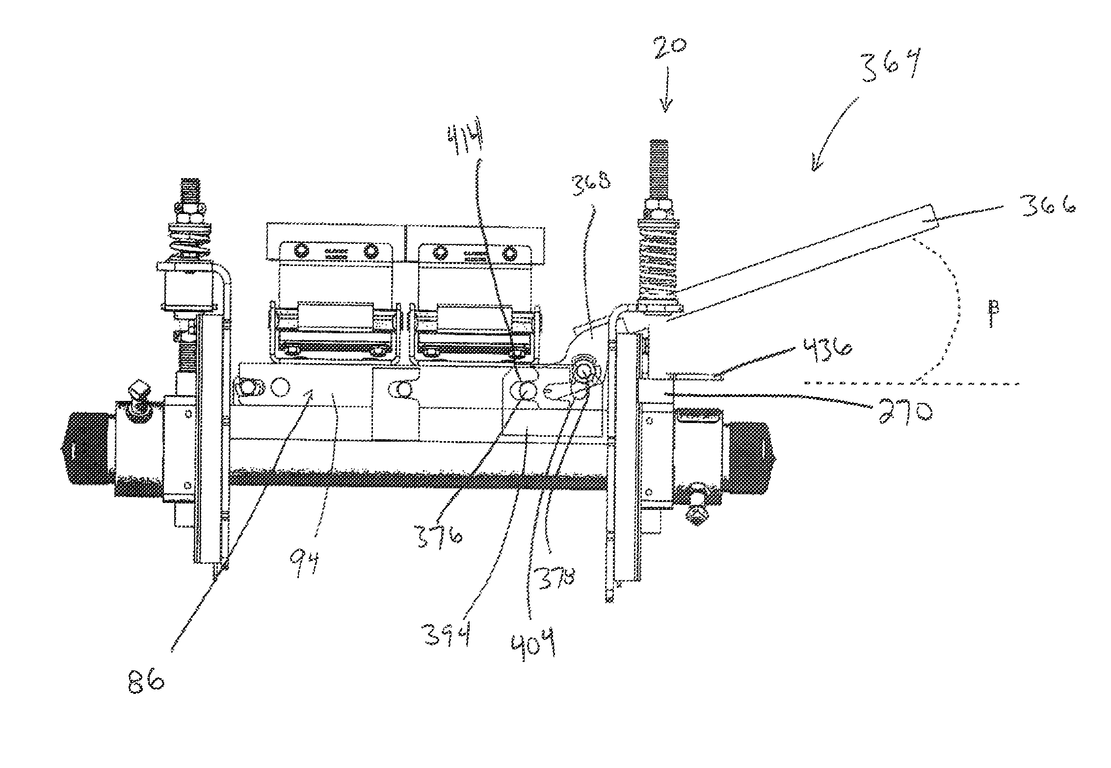
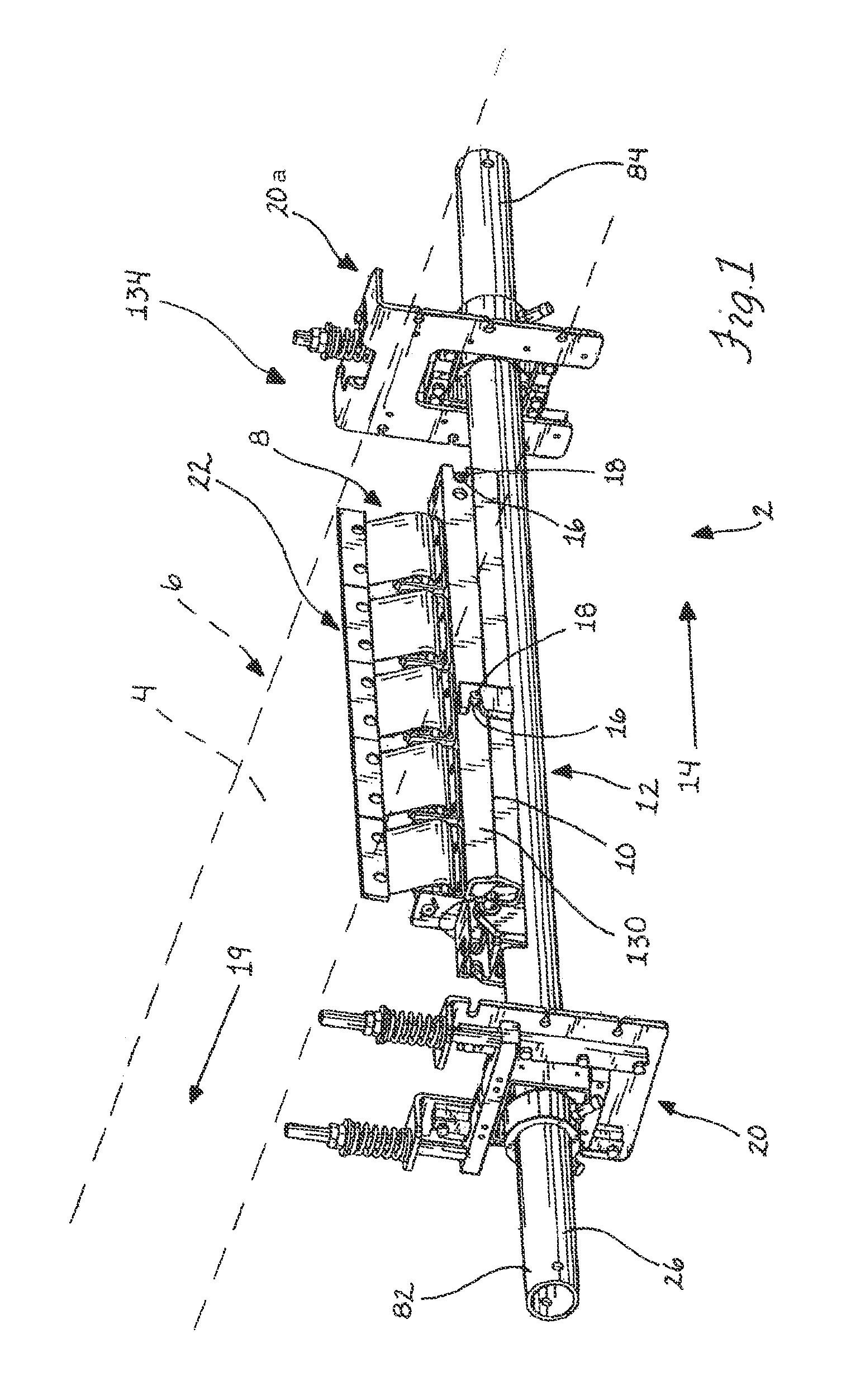
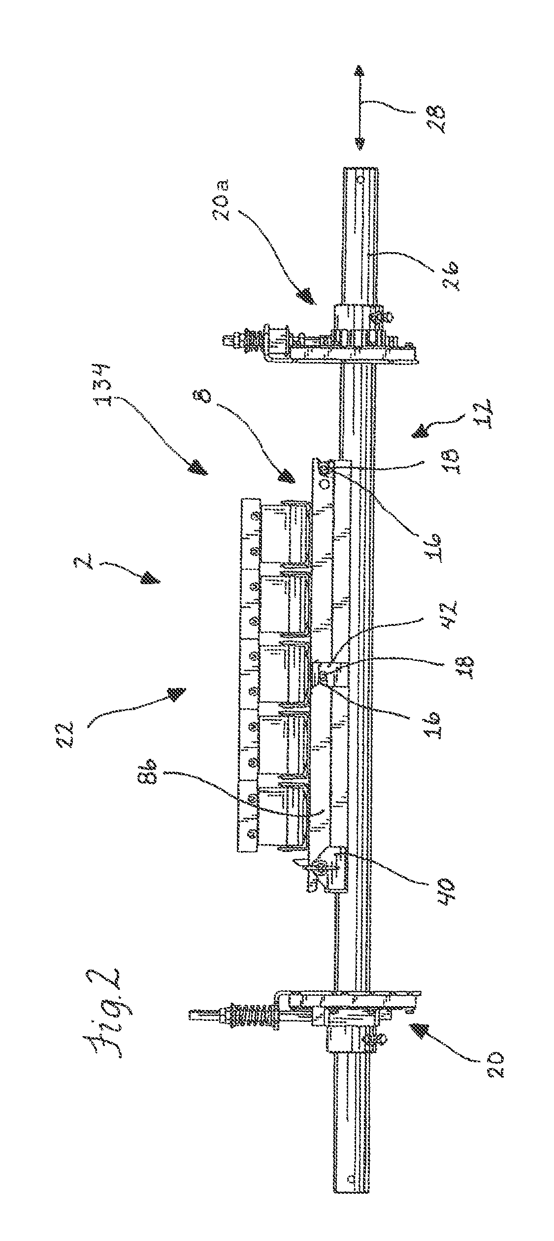
[0075]In FIGS. 1 and 2, a removable cartridge cleaner assembly 2 is shown for a conveyor belt 4 that can be located adjacent the return run 6 or the head pulley of the conveyor belt 4. The removable cartridge cleaner assembly 2 includes a rail or cartridge assembly 8 biased or urged into tight engagement with an upper mounting surface 10 of an elongate support assembly 12 extending in a lateral assembly direction 14 under and across the conveyor belt 4. One or both of the rail assembly 8 and elongate support assembly 12 include biasing or guide surfaces 16 configured to extend generally obliquely to the lateral assembly direction 14 and engage or be engaged by lateral or securing members 18 of the rail and support assemblies 8, 12 configured to extend generally orthogonal to the lateral assembly direction 14 and parallel to the belt travel direction 19. The tight engagement of the rail and support assemblies 8, 12 minimizes vibration and space between the rail and support assemblies...


PUM

PropertyMeasurementUnit
lengthaaaaaaaaaa
insertion forceaaaaaaaaaa
release forceaaaaaaaaaa

Abstract

A removable cartridge cleaner assembly is provided that has an insertion device for ease in installing an elongate cartridge assembly carrying belt cleaner assemblies onto an elongate support extending across a conveyor belt in an operative position thereon. In one form, an elongate lever handle pivotally connected to the elongate cartridge assembly can be used to generate a leveraged insertion force, preferably by an operator that does not need to reach into the operating envelope of the conveyor system, e.g. beyond tensioning mechanisms or under the belt. The handle and the cartridge assembly can have an over center locking mechanism therebetween for providing the operator tactile feedback as to when pivoting of the lever handle has caused the cartridge assembly to be shifted to its operative position on the support.

Description

CROSS REFERENCE TO RELATED APPLICATIONS[0001]This application is a continuation-in-part of U.S. patent application Ser. No. 12 / 421,988, filed Apr. 10, 2009, and claims the benefit of the filing date of U.S. Provisional Application 61 / 044,050, filed Apr. 10, 2008, and U.S. Provisional Application 61 / 308,840, filed Feb. 26, 2010, each of which are hereby incorporated by reference in their entirety herein.FIELD OF THE INVENTION[0002]The invention relates to a cleaner assembly for a conveyor belt and, more particularly, to a cleaner assembly that can be easily installed under a conveyor belt and removed therefrom.BACKGROUND OF THE INVENTION[0003]A variety of industries utilize conveyor belts to transport goods and materials from one place to another. Generally, material is deposited onto the upstream end of the upper or carry run of a belt and is discharged at the downstream end of the carry run of the belt. However, small amounts of material often remain adhered to the belt surface. Th...

Claims


Application Information

Patent Timeline
Patent Type & Authority Patents(United States)
IPC IPC(8): B65G45/12
CPCB65G45/16B65G45/12Y10T29/49863
Inventor KUIPER, DANIEL J.DEVRIES, BRETT E.WESTPHALL, GREGORY LEEGILMAN, RICHARD W.
Owner FLEXIBLE STEEL LACING
Why Eureka
Try Eureka