

Method for manufacturing an optical lens by additive manufacturing and corresponding intermediate optical element
- Summary
- Abstract
- Description
- Claims
- Application Information
AI Technical Summary
Benefits of technology
Problems solved by technology
Method used
Image

Examples
first embodiment
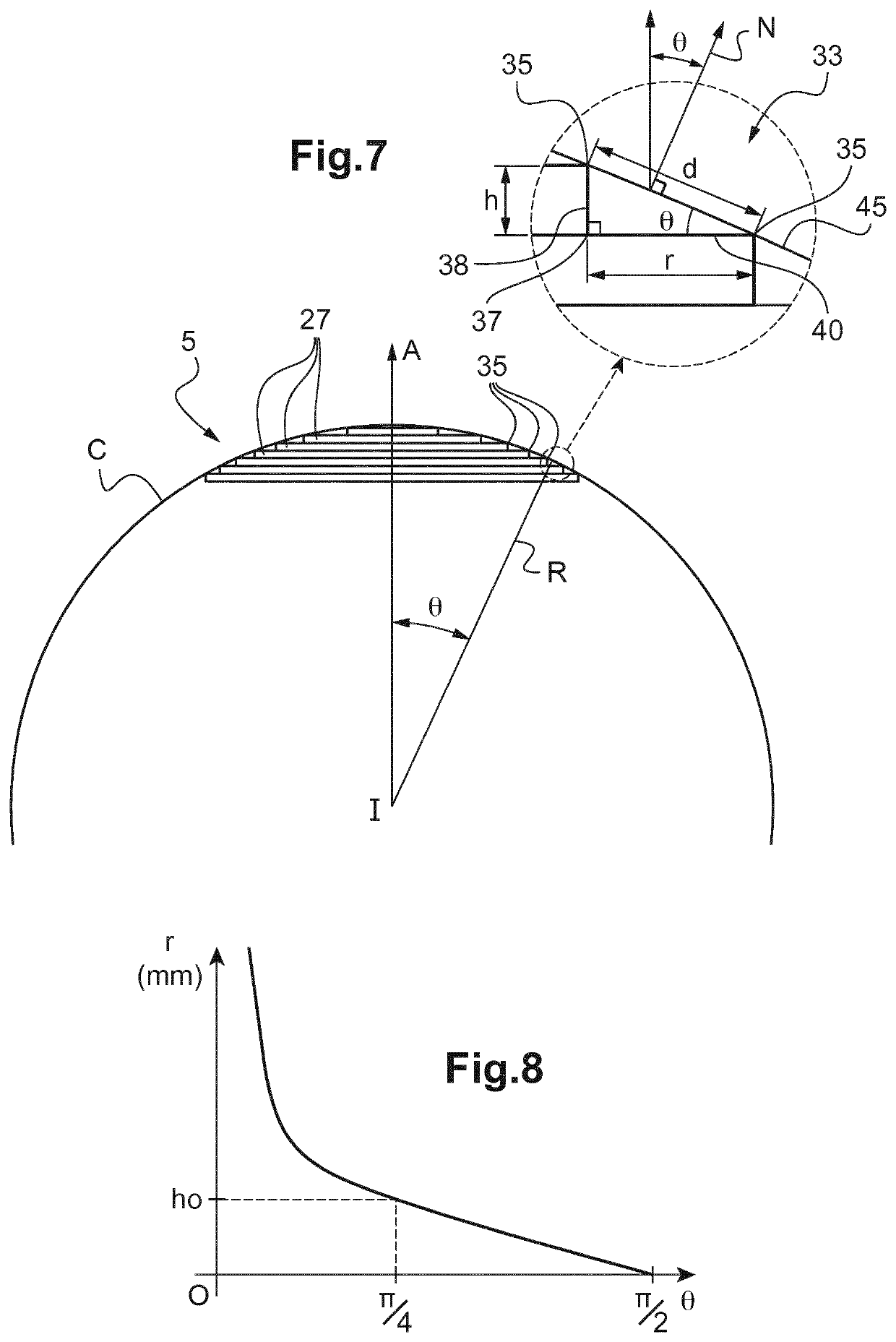
[0063]FIG. 11 is a graph illustrating the variation of the geometrical parameter for the method,
[0064]FIG. 12 is a graph illustrating the variation of the geometrical parameter for a variant of the first embodiment of the method,
second embodiment
[0065]FIG. 13 is a graph illustrating the variation of the geometrical parameter for the method.
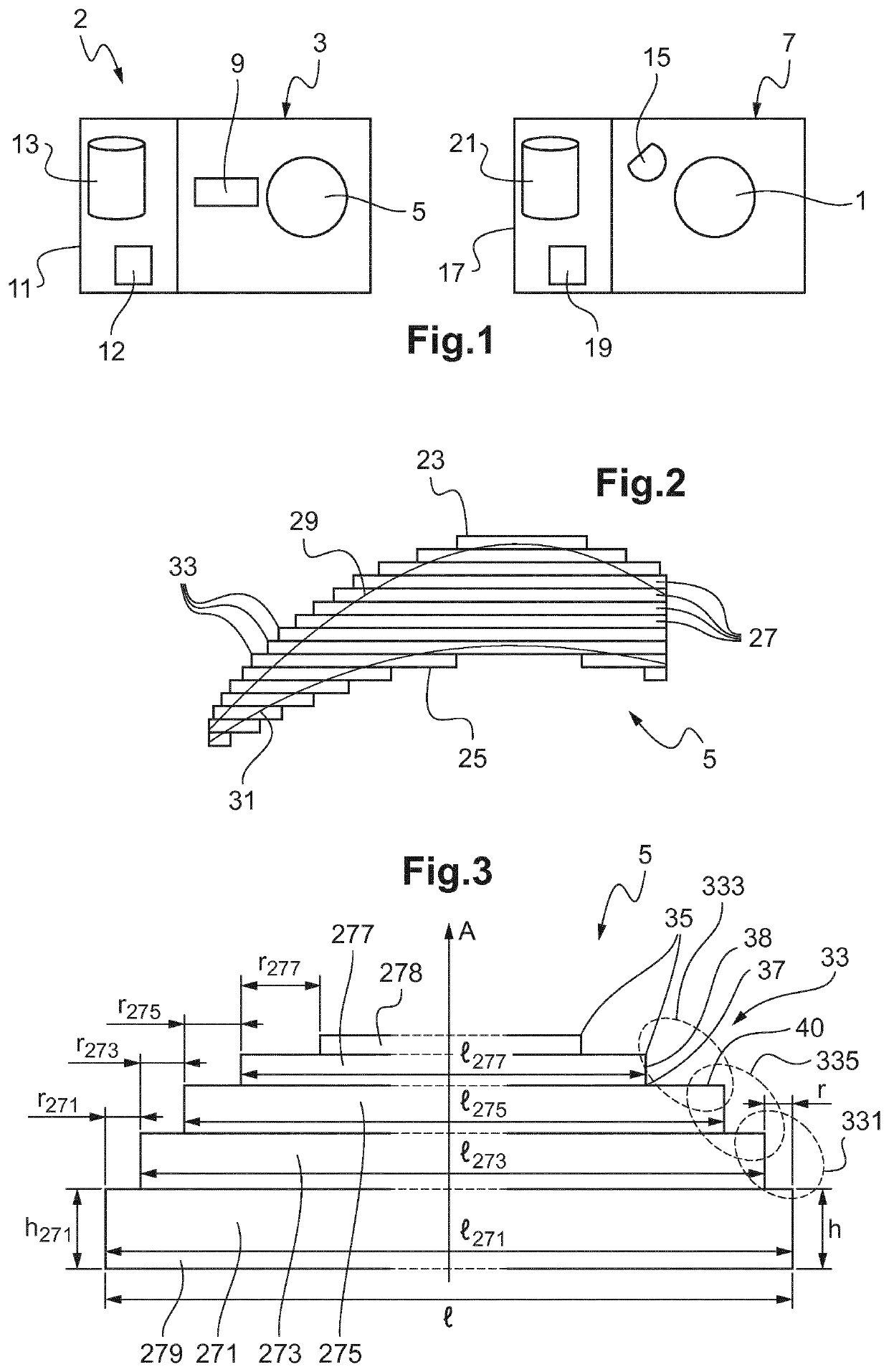
[0066]FIG. 1 shows a system 2 for manufacturing an optical lens 1. The system includes an additive manufacturing machine 3 for producing an intermediate optical element 5. The system includes a smoothing machine 7 for smoothing intermediate element 5 into optical lens 1.
[0067]Additive manufacturing machine 3 comprises a depositing device 9. Depositing device 9 is suitable for manufacturing intermediate optical element 5 using an additive manufacturing technology. The expression “additive manufacturing technology” refers to processes that manufacture solid objects by juxtaposing volume elements or voxels. In the case of the present invention, intermediate optical element 5 is thus manufactured volume element by volume element, layer by layer. The additive manufacturing technology may be in practice stereolithography (SLA) or polymer jetting or continuous liquid interface production (CLIP) ...
PUM
| Property | Measurement | Unit |
|---|---|---|
| Time | aaaaa | aaaaa |
| Thickness | aaaaa | aaaaa |
| Length | aaaaa | aaaaa |
Abstract
Description
Claims
Application Information