Portable generator and battery charger verification control method and system

a generator and battery charger technology, applied in the field of verification control methods and systems of portable generators and battery chargers, can solve the problems of increased maintenance and repair costs, welding systems lack the intelligence to supply power correctly and safely to other applications,

Active Publication Date: 2014-06-24
ILLINOIS TOOL WORKS INC
View PDF26 Cites 26 Cited by
  • Summary
  • Abstract
  • Description
  • Claims
  • Application Information

AI Technical Summary

Problems solved by technology

In addition, the independence of the two units may result in an increased amount of maintenance and repair costs due to duplication of parts.
In addition, welding systems lack the intelligence to supply power correctly and safely to other applications, such as batteries.

Method used


Image

  • Portable generator and battery charger verification control method and system
  • Portable generator and battery charger verification control method and system
  • Portable generator and battery charger verification control method and system

Examples


Embodiment Construction

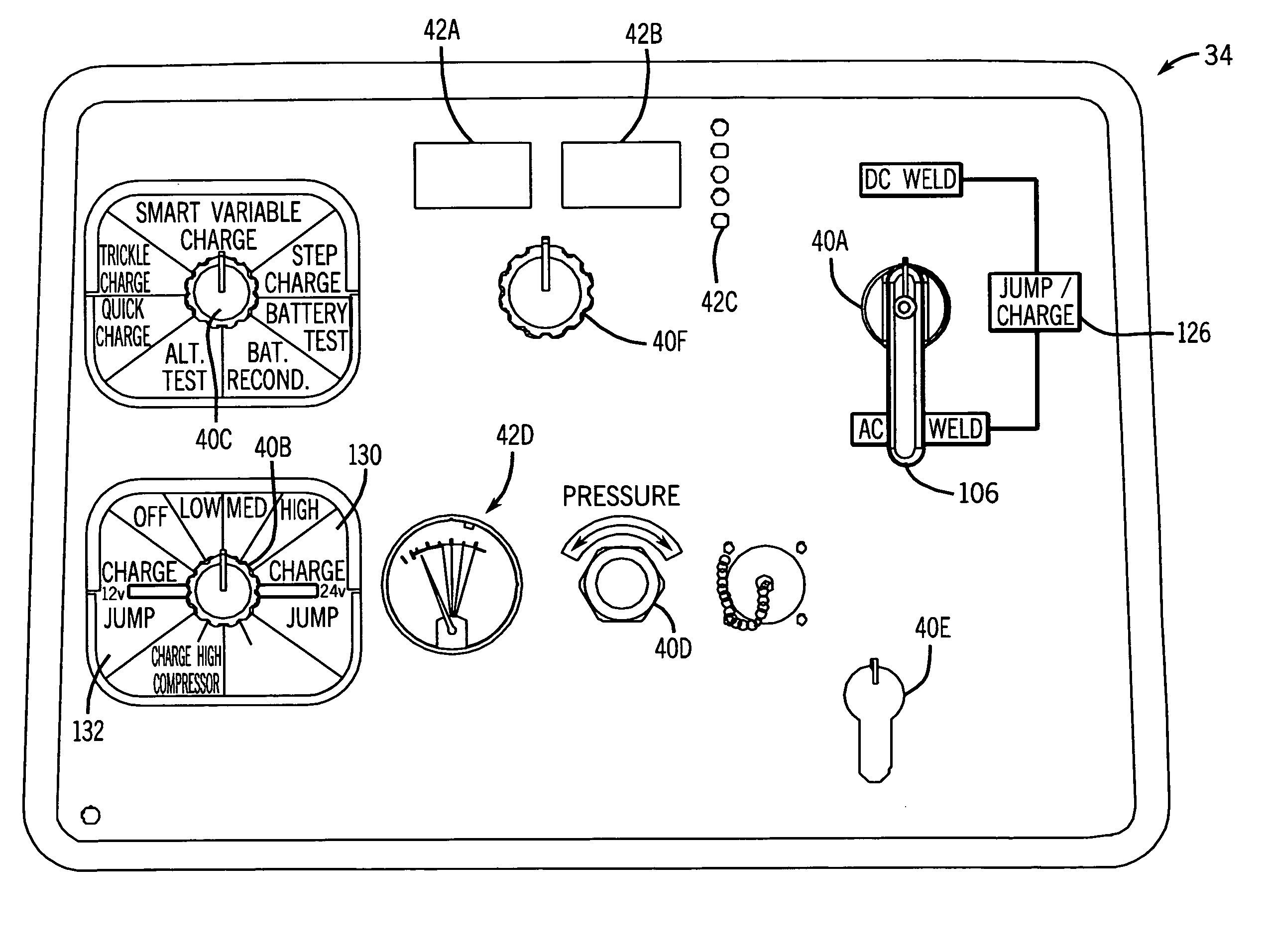
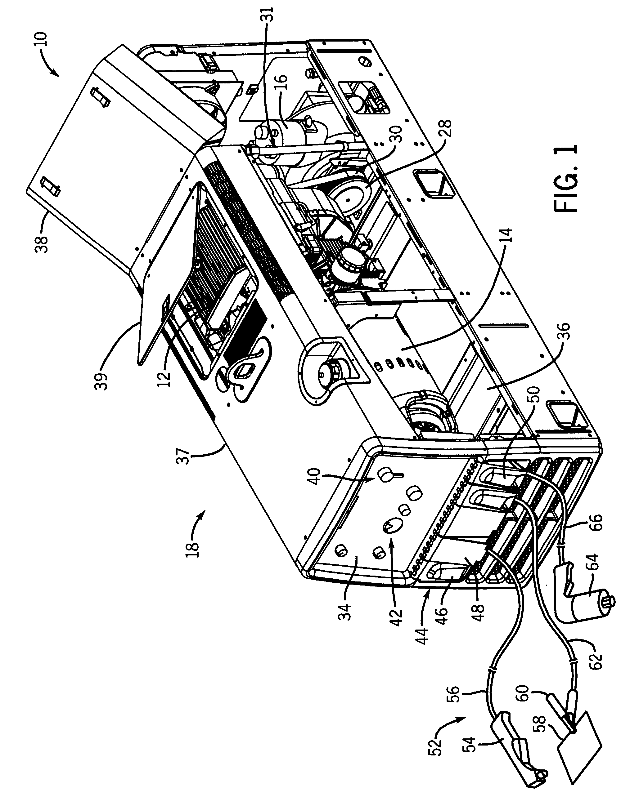
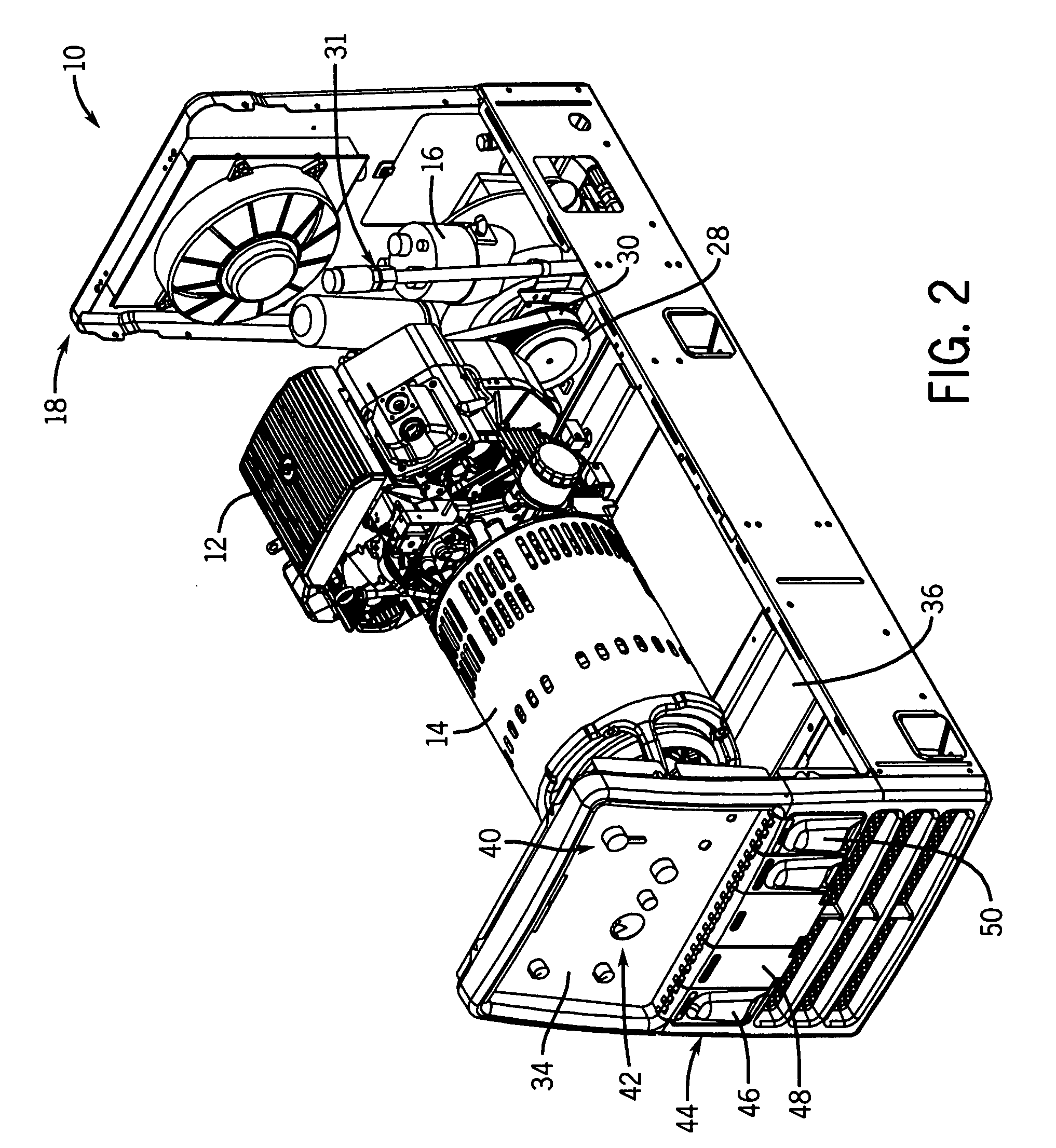
[0015]Referring now to the drawings, FIGS. 1-3 illustrate an intelligent engine-driven welding generator / charger / compressor system 10 having an engine 12 drivingly coupled to a welding generator 14 and an air compressor 16 in a single enclosure 18 in accordance with an exemplary embodiment of the present technique. As discussed in detail below, the single enclosure 18 includes multiple functionalities all in one portable system to improve productivity and reduce space consumption. Specifically, the system 10 is configured to output compressed air and electrical power for a variety of applications, including welding, cutting, battery charging, jump starting, air-powered tools, and so forth. Moreover, the system 10 includes intelligence (e.g., logic in software and / or hardware) to adjust the outputs based on various feedback of the system 10 and the external device receiving the electrical power and / or compressed air from the system 10. For example, the system 10 does not blindly prov...


PUM

PropertyMeasurementUnit
voltageaaaaaaaaaa
voltageaaaaaaaaaa
voltageaaaaaaaaaa

Abstract

A system may include a portable welding unit having an engine, a generator coupled to the engine, a compressor coupled to the engine, and a smart battery charger coupled to the generator. The smart battery charger may be configured to monitor a temperature of a battery, an ambient temperature, a battery charge time, or a combination thereof. The smart battery charger may also be configured to adjust an output based on a battery type, a battery voltage rating, a sensed feedback, a battery test, or a combination thereof.

Description

BACKGROUND[0001]The invention relates generally to welding systems and more particularly to welding systems utilizing an engine coupled to an air compressor and welding generator in a single unit.[0002]Welding systems generally use an electrical current (e.g., welding current) to perform welding. The electrical current may be provided by an electrical power source (such as a power grid or battery) or an electrical generator coupled to a mechanical power source. Examples of mechanical power sources include engines that output power via a rotating drive shaft. Typically, the drive shaft is coupled to other devices that consume the energy provided by the rotating drive. For instance, welding systems often include internal combustion engines (such as gas or diesel engines) and an alternator or generator configured to convert the mechanical energy generated by the engine into electrical energy (e.g., electrical current). These systems are often referred to as engine-driven welding genera...

Claims


Application Information

Patent Timeline
Patent Type & Authority Patents(United States)
IPC IPC(8): H05B7/11B23K9/10
CPCB23K9/10B23K9/1006
Inventor FOSBINDER, DANIEL, C.
Owner ILLINOIS TOOL WORKS INC
Why Eureka
Try Eureka