
Control method of a wind turbine generator

a technology of wind turbine generator and control method, which is applied in the direction of electric generator control, machine/engine, dynamo-electric converter control, etc., can solve the problems of reducing and minimising the service life of the wind turbine generator, inability to limit the power captured with sufficient speed, and limit the voltage used

Active Publication Date: 2014-06-24
NORDEX ENERGY SPAIN SA
View PDF11 Cites 2 Cited by
  • Summary
  • Abstract
  • Description
  • Claims
  • Application Information

AI Technical Summary

Benefits of technology

The invention is a method to control a wind turbine generator that allows it to operate at higher speeds for longer periods of time, improving its efficiency and lifespan.

Problems solved by technology

Under exceptional circumstances, such as for example strong gusts of wind in which there is a sudden, sharp increase in wind speed, wind rotor “overspeeds” can occur, i.e. the rotor rotates at higher speeds than for which it was designed, due to the fact that the pitch system is not dimensioned to increase the blade pitch and, consequently, it is incapable of limiting the power captured with sufficient speed.
In addition, in both cases extreme and fatigue loads are produced that considerably reduce and minimise the service life of the wind turbine generator.
Specifically, both in doubly-fed wind turbine generators (DFIG or doubly-fed induction generator) and in wind turbine generators connected to the grid through a full power converter (FC), the limit used is the voltage at the converter terminals on the machine side due to the fact that, upon exceeding certain safety margins with respect to the voltage of the DC bus thereof, control of the wind turbine generator is lost.
The variations in rotor speed negatively affect both the life span of the wind turbine generator and speed control using pitch, whereupon the bandwidth of the corresponding control loop is reduced: on responding to variations in rotational speed in relation to an average speed value, the capacity to control said average rotational speed using the pitch system leads to more frequent stops due to overspeed.

Method used


Image

  • Control method of a wind turbine generator
  • Control method of a wind turbine generator
  • Control method of a wind turbine generator

Examples


Embodiment Construction

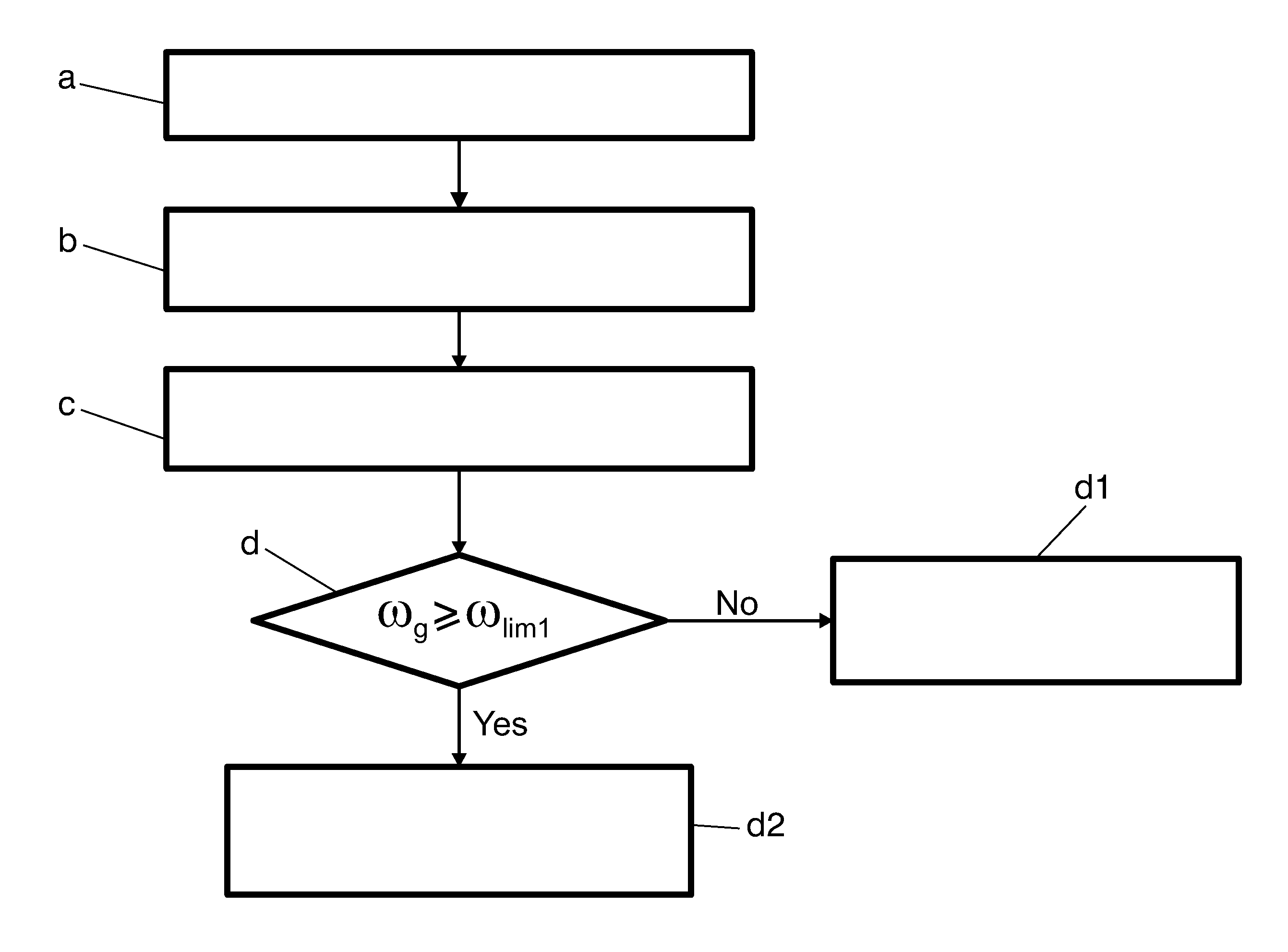
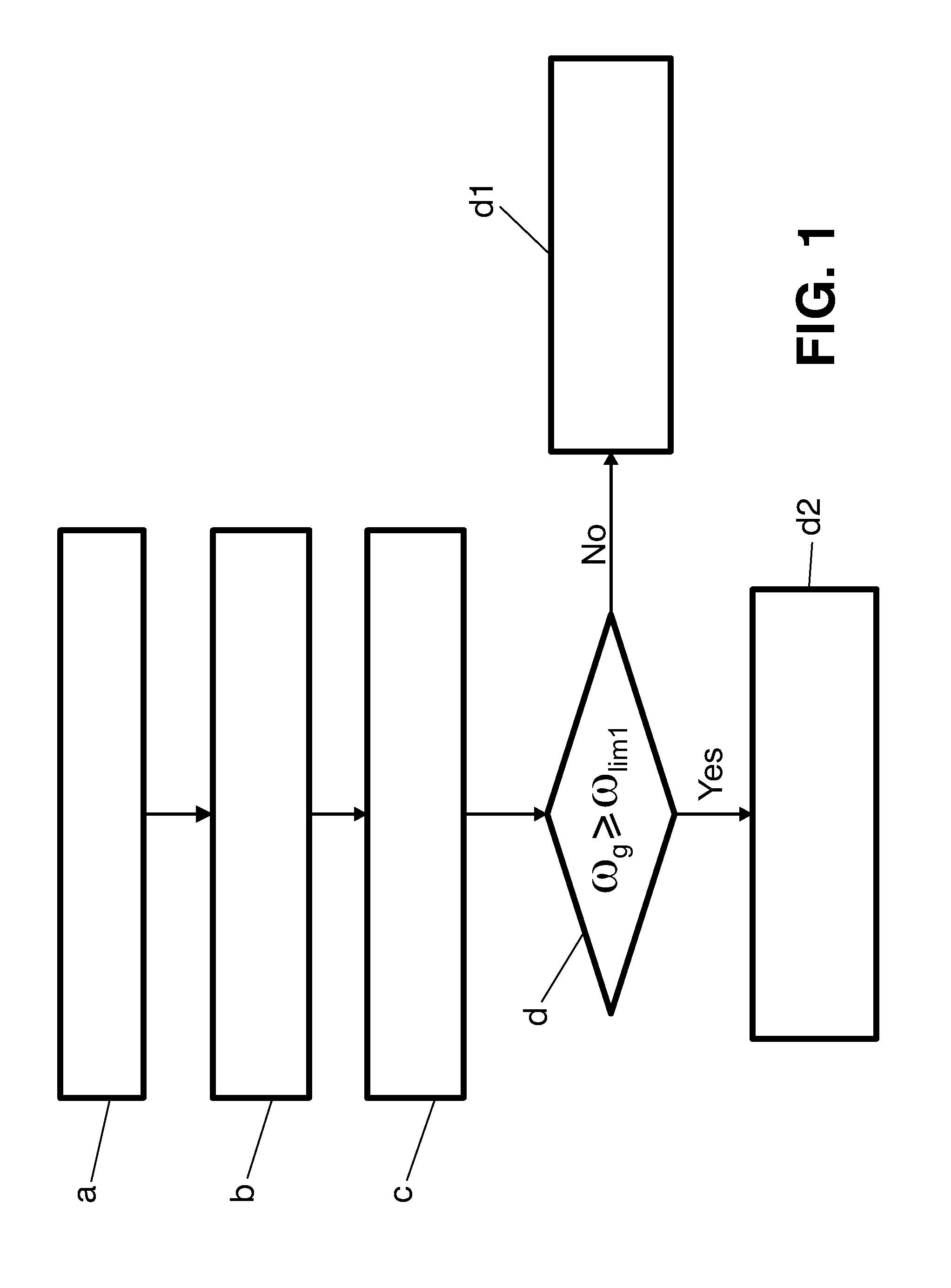
[0010]The present invention resolves the aforementioned drawbacks by providing a control method of a wind turbine generator in order to obtain a wide transition speed range in said wind turbine generator. More specifically, said control method substantially reduces the number of wind turbine generator stops in those cases where wind speed exceeds a certain threshold value and causes “overspeeds” in the wind rotor of said wind turbine generators. Further, in addition to increasing the speed range and maximising operation of the wind turbine generators, the control method object of the invention also lengthens their service life, due to the fact that the extreme and fatigue loads to which the wind turbine generators are subject, resulting from the constant stops and disconnections thereof as a consequence of strong gusts of wind, are reduced.

[0011]The control method described herein is applicable to wind turbine generators of the type comprising a wind rotor, at least two blades linke...


PUM


Abstract

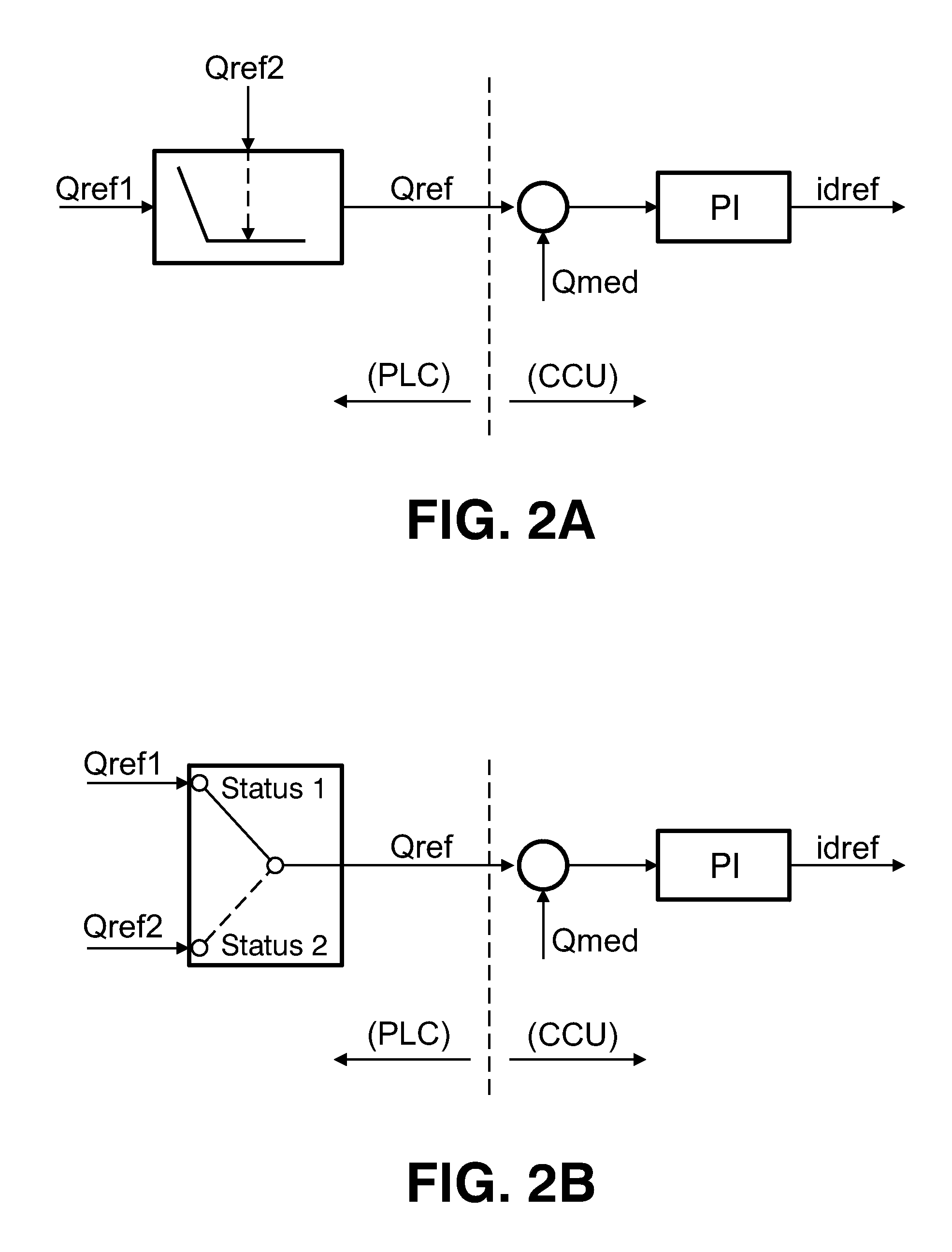
The control method of a wind turbine generator increases the speed range of wind turbine generators, maximizing the operation and efficiency thereof, in addition to lengthening their service life, on minimizing the extreme and fatigue loads to which the wind turbine generators are subject, and which are due mainly to the stops and disconnections thereof as a result of strong gusts of wind. More specifically, the control method of the present invention stands out essentially for being based on the control of the reactive current circulating through the electric generator, said reactive current control being carried out in accordance with the rotational speed (ωg) for the purpose of reducing the voltage at the converter terminals on the generator side, or rotor voltage (VR), which ultimately allows a transitional increase in the speed range of the wind turbine generator.

Description

OBJECT OF THE INVENTION[0001]The present invention relates to the field of wind turbine generators and, more specifically, to methods for controlling and / or regulating the power generated.[0002]The main object of the present invention is a control method of a wind turbine generator which transitionally increases its speed range and, therefore, extends the operation and efficiency of the wind turbine generator to above the overspeed threshold value.BACKGROUND OF THE INVENTION[0003]At present, renewable energy sources have become consolidated as the strongest alternative to conventional energy sources for generating electricity, one of the most efficient of which is wind energy. Wind energy is that which allows generation of electricity using generators or wind turbines. Said wind turbine generators are basically composed of a tower, a gondola disposed at the top of the tower that houses the electric generator and a rotor disposed at the front of the gondola, formed in turn by at leas...

Claims


Application Information

Patent Timeline
Patent Type & Authority Patents(United States)
IPC IPC(8): F03D9/00
CPCH02J3/18H02P21/0089F03D7/042Y02E10/723H02P9/48Y02E40/30Y02E10/72Y02E10/76G05D13/46
Inventor GARCIA SAYES, JOSE MIGUELARLABAN GABEIRAS, TERESAN NEZ POLO, MIGUEL
Owner NORDEX ENERGY SPAIN SA
Learn More