Sensorless motor apparatus, back EMF detector and detection method thereof

a sensorless motor and detector technology, applied in the direction of motor/generator/converter stopper, electronic commutator, dynamo-electric converter control, etc., can solve the problems of increased cost of disposing of sensorless motor equipment, reduced competition of products, and complicated operation, so as to achieve simple and efficient detection

Active Publication Date: 2014-06-24
SEMICON COMPONENTS IND LLC
View PDF1 Cites 1 Cited by
  • Summary
  • Abstract
  • Description
  • Claims
  • Application Information

AI Technical Summary

Benefits of technology

[0006]Accordingly, the present invention is directed to a back EMF detector for a motor, so as to obtain a back EMF detection result through simple and efficient detection.
[0007]The present invention provides a sensorless motor apparatus, so as to obtain a back EMF detection result through simple and efficient detection by a back EMF detector.
[0008]The present invention provides a method for detecting a back EMF for a motor, so as to obtain a back EMF detection result through simple and efficient detection.
[0012]Based on the above description, in the present invention, a simple circuit formed by the resistance providers is disposed, in which the resistance values of the first to third resistance providers are determined by at least one characteristic parameter of the motor. Then the driving voltages and the detection voltages generated based on the driving current flowing via the circuit formed by the resistance providers, and the back EMF detection results corresponding to the driving voltages are obtained at the output terminal of the circuit formed by the resistance providers. In this way, the back EMF does not need to detect through complicated computation by software and hardware any more, so that the cost demand of the sensorless motor apparatus can be effectively lowered.

Problems solved by technology

In this calculation manner, in addition to a look up table (LUT) of a certain size, some complicated operations are required.
That is to say, the cost for disposing the sensorless motor apparatus is accordingly increased, thus correspondingly lowering the competition of the product.

Method used


Image

  • Sensorless motor apparatus, back EMF detector and detection method thereof
  • Sensorless motor apparatus, back EMF detector and detection method thereof
  • Sensorless motor apparatus, back EMF detector and detection method thereof

Examples


Embodiment Construction

[0021]Reference will now be made in detail to the present embodiments of the invention, examples of which are illustrated in the accompanying drawings. Wherever possible, the same reference numbers are used in the drawings and the description to refer to the same or like parts.

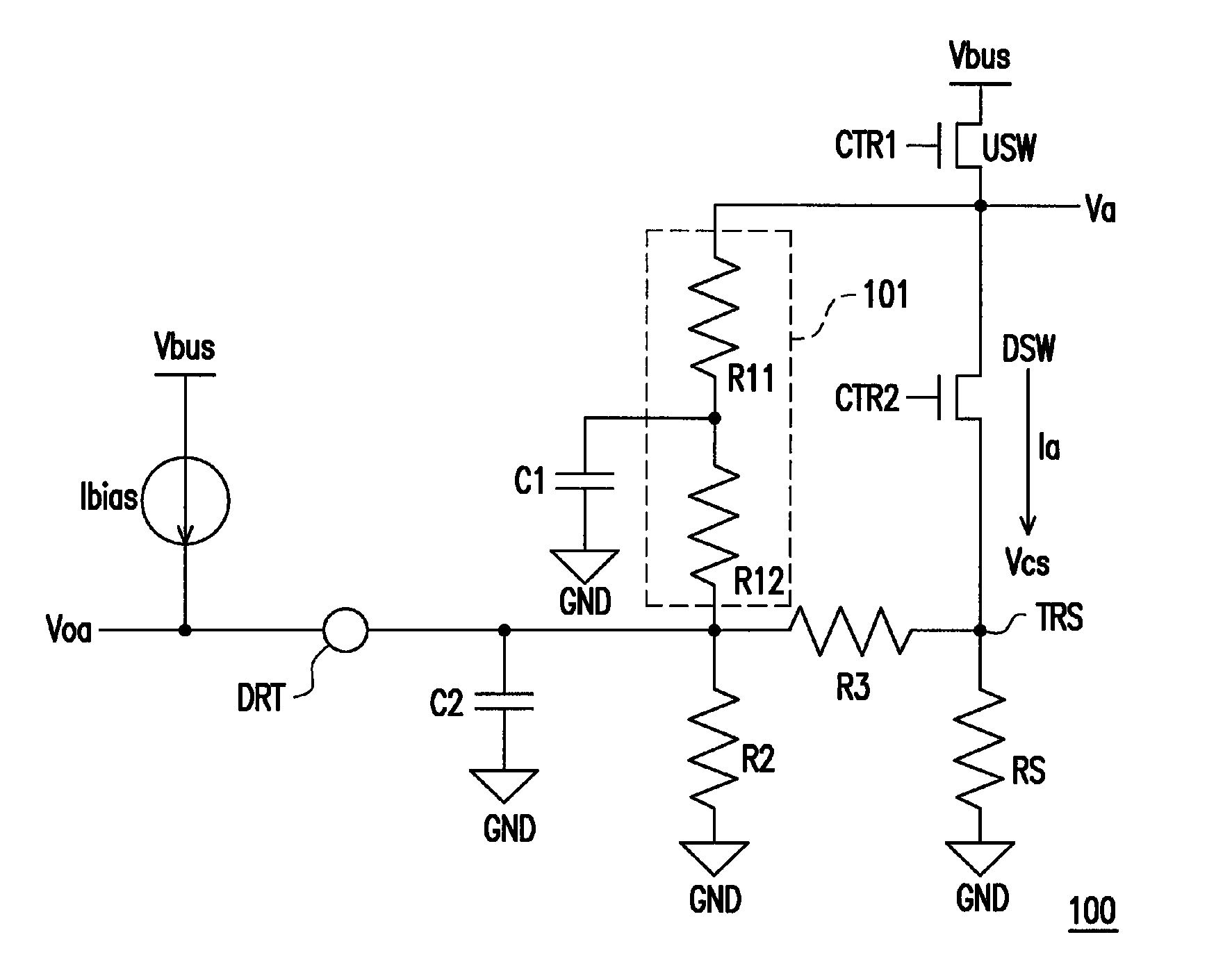
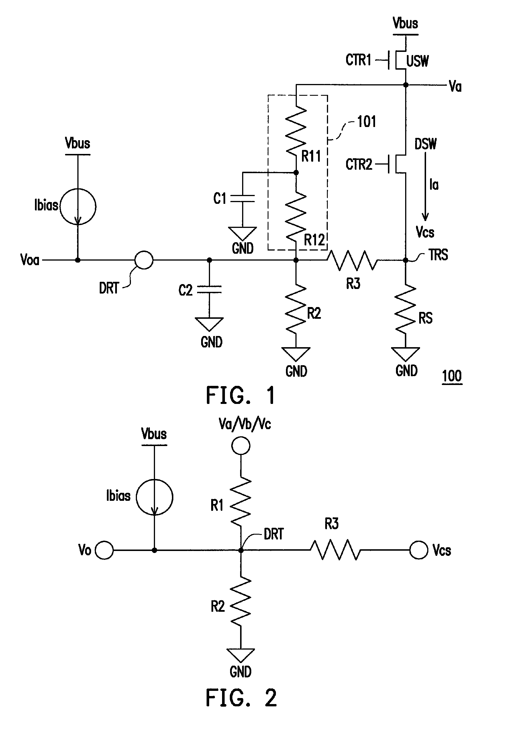
[0022]FIG. 1 is a schematic view of a back EMF detector 100 for a motor according to an embodiment of the present invention. Referring to FIG. 1, the back EMF detector 100 includes an upper switch USW, a lower switch DSW, a current sensing resistor RS, resistance providers 101, R2 and R3, a bias current source Ibias, and filter capacitors C1 and C2. The upper switch USW includes a first terminal coupled to a reference voltage source Vbus, and a second terminal coupled to a driving voltage Va, and is controlled by a control signal CTR1. The lower switch DSW includes a first terminal coupled to the second terminal of the upper switch USW, and is controlled by a control signal CTR2. The current sensing resistor R...


PUM


Abstract

A back electromotive force (EMF) detector for a motor is disclosed. The back EMF detector includes an upper switch, a lower switch, a current sensing resistor and a first to third resistance providers. The upper and lower switches are controlled by a first and a second control signal respectively. The current sensing resistor coupled between the lower switch and a reference ground voltage. A first terminal of the first resistance provider coupled to the upper switch, and a back EMF detection result is generated at a second terminal of the first resistance provider. The second resistance provider coupled between the reference ground voltage and the first resistance provider. The third resistance provider is coupled between the coupled terminal of the first and second resistance provider and the lower switch. Wherein, the first to the third resistance providers are determined by at least one characteristic parameter of the motor.

Description

BACKGROUND OF THE INVENTION[0001]1. Field of the Invention[0002]The present invention generally relates to a sensorless motor apparatus, in particular, to a back electromotive force (EMF) detector of a sensorless motor apparatus.[0003]2. Description of Related Art[0004]In the prior art, in order to achieve the disposition of a sensorless motor apparatus, the deduction of the state of a rotor of the motor is an important subject. It is a common practice to convert a virtual sensing signal of the motor rotor through a back EMF of a motor.[0005]In the prior art, the virtual sensing signal is obtained through an operation performed by using parameters of the motor in combination with multiple electrical and mechanic properties of the motor in operation. In this calculation manner, in addition to a look up table (LUT) of a certain size, some complicated operations are required. In order to deal with such calculation requirements, a high-efficiency processor (for example, a Digital Signal...

Claims


Application Information

Patent Timeline
Patent Type & Authority Patents(United States)
IPC IPC(8): H02P6/18H02P6/08
CPCH02P6/085H02P6/182
Inventor LIN, YI-CHIYIN, CHIH-PINGYANG, SHIH-JEN
Owner SEMICON COMPONENTS IND LLC
Why Eureka
Try Eureka