
Antenna testing method and device of electronic equipment and electronic equipment

A technology for electronic equipment and testing devices, applied in directions such as antenna radiation patterns, can solve the problems of low detection efficiency and high production costs

Pending Publication Date: 2021-01-29
HEFEI LCFC INFORMATION TECH
View PDF6 Cites 3 Cited by
  • Summary
  • Abstract
  • Description
  • Claims
  • Application Information

AI Technical Summary

Problems solved by technology

[0003] However, this type of electronic equipment needs to assemble its multiple antennas during the production process, and in order to ensure the quality of the antenna assembly, it is necessary to detect the installation of the antennas of the electronic equipment, but the detection process is usually done by using other external equipment. Each antenna is tested separately, the detection efficiency is low, and the production cost is high

Method used


Image

  • Antenna testing method and device of electronic equipment and electronic equipment
  • Antenna testing method and device of electronic equipment and electronic equipment
  • Antenna testing method and device of electronic equipment and electronic equipment

Examples


Embodiment Construction

[0040] Various aspects and features of the invention are described herein with reference to the accompanying drawings.

[0041] It should be understood that various modifications may be made to the embodiments of the inventions herein. Accordingly, the above description should not be viewed as limiting, but only as exemplifications of embodiments. Those skilled in the art will envision other modifications within the scope and spirit of the invention.

[0042] The accompanying drawings, which are incorporated in and constitute a part of this specification, illustrate embodiments of the invention and, together with the general description of the invention given above and the detailed description of the embodiments given below, serve to explain the invention. principle.

[0043] These and other characteristics of the invention will become apparent from the following description of preferred forms of embodiment given as non-limiting examples with reference to the accompanying dr...


PUM


Abstract

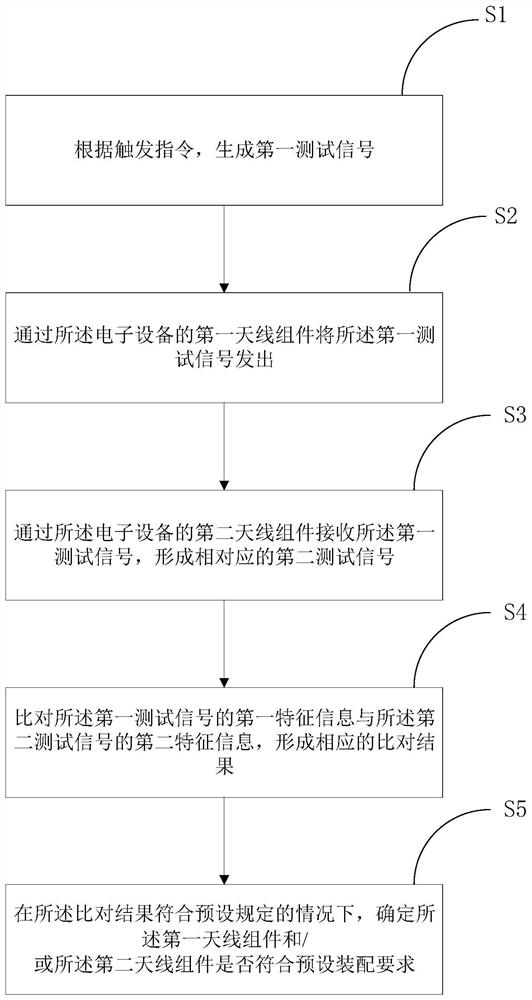
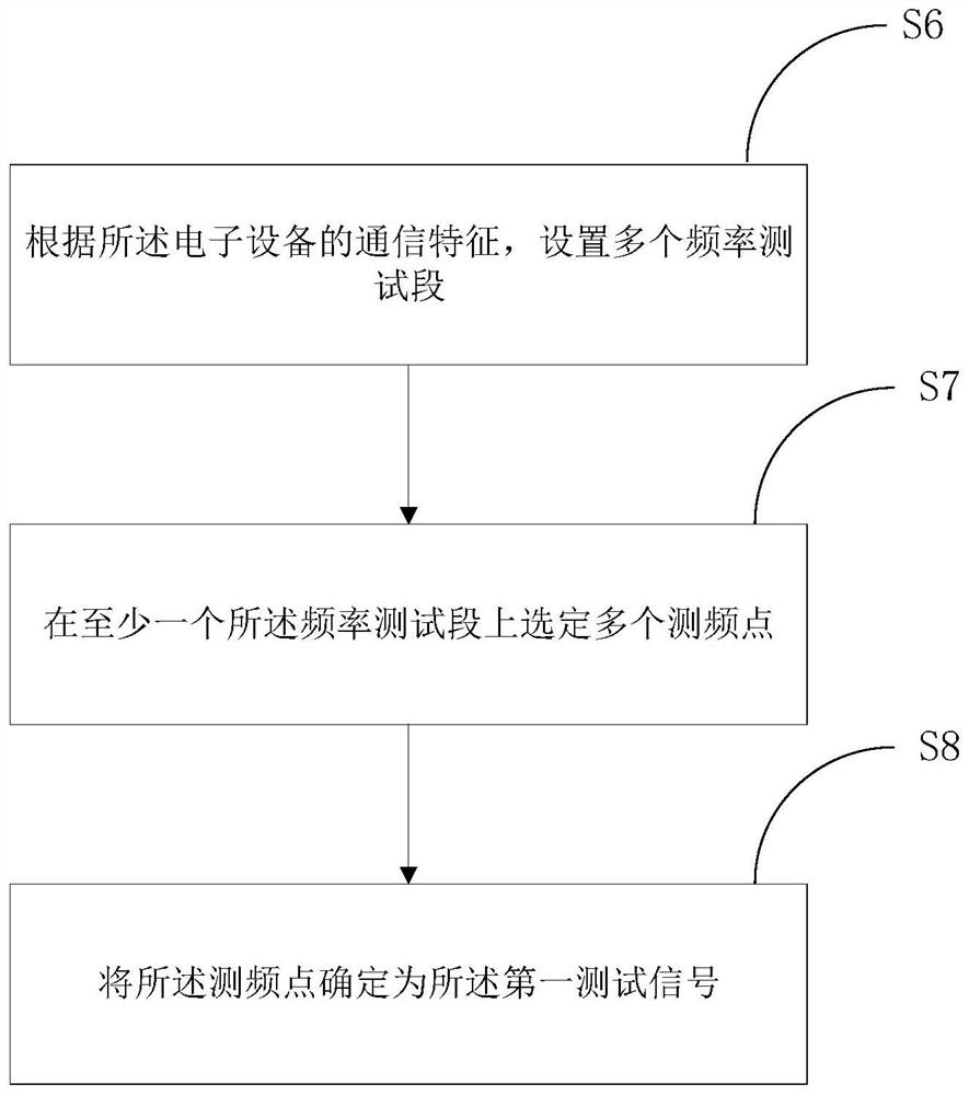
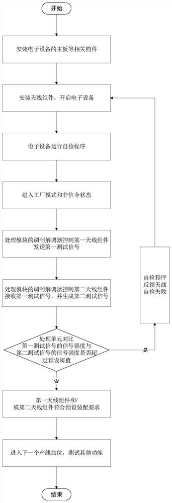
The invention discloses an antenna test method and device for electronic equipment and the electronic equipment, and the method comprises the steps: generating a first test signal according to a triggering instruction; sending out the first test signal through a first antenna assembly of the electronic equipment; receiving the first test signal through a second antenna assembly of the electronic equipment to form a corresponding second test signal; comparing the first characteristic information of the first test signal with the second characteristic information of the second test signal to form a corresponding comparison result; and determining whether the first antenna assembly and / or the second antenna assembly meet / meets a preset assembly requirement or not under the condition that thecomparison result meets the preset regulation. According to the method, the installation condition of the antenna can be conveniently and efficiently detected in the assembling process of the antennaof the electronic equipment, automatic detection can be achieved without the help of other detection equipment except the electronic equipment, the detection efficiency is improved, and the detectioncost is effectively reduced.

Description

technical field [0001] The invention relates to the field of communication testing of electronic equipment, in particular to an antenna testing method and device for electronic equipment and electronic equipment. Background technique [0002] In the process of assembling antennas of electronic devices such as computers, routers, and mobile phones, it is necessary to detect the assembly status of the antennas. However, with the introduction of new technologies such as 5G and wifi6, more and more electronic devices require multiple sets of different antenna components to realize the designed transceiver mechanism. For example, in order to support the uplink and downlink of dual-antenna 2X2 MIMO, this means that electronic devices will be equipped with two sets of antennas under the same working frequency band and communication system. [0003] However, this type of electronic equipment needs to assemble its multiple antennas during the production process, and in order to ensu...

Claims


Application Information

Patent Timeline
IPC IPC(8): G01R29/10
CPCG01R29/10
Inventor 陆康吴枝强张银抢
Owner HEFEI LCFC INFORMATION TECH
Learn More