Irrigated catheter

a catheter and irrigated technology, applied in the field of catheters, can solve the problems of affecting the cooling effect of the catheter tip,

Active Publication Date: 2014-07-01
ST JUDE MEDICAL ATRIAL FIBRILLATION DIV
View PDF25 Cites 33 Cited by
  • Summary
  • Abstract
  • Description
  • Claims
  • Application Information

AI Technical Summary

Benefits of technology

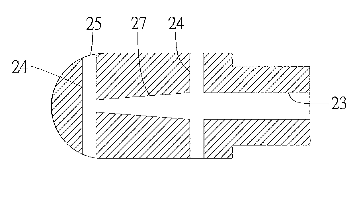
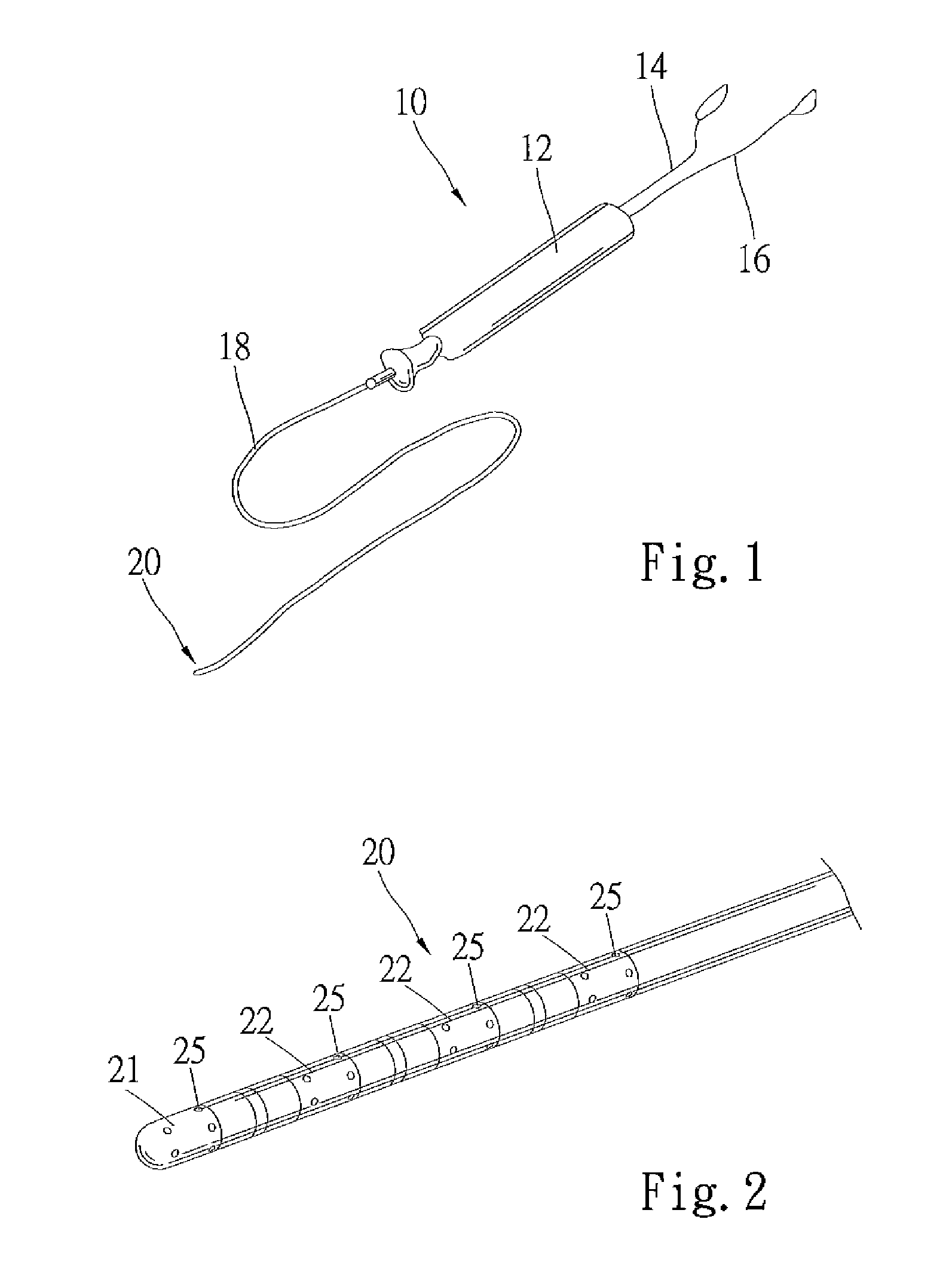
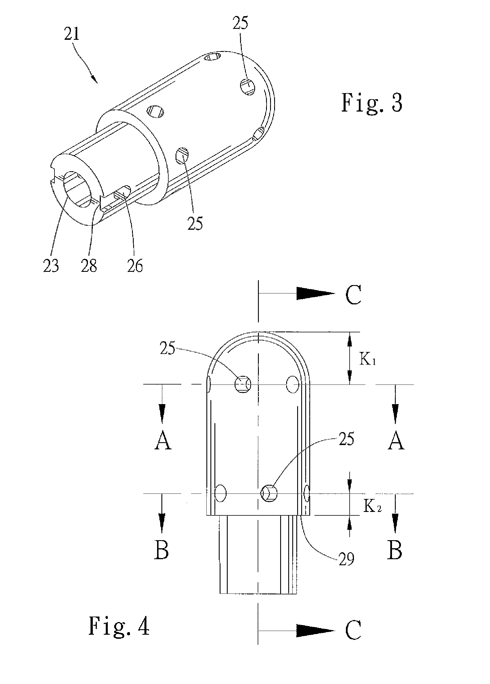
[0016]Further, the balloons can be positioned opposite to elution holes and / or electrodes so that the inflatable balloon can assist in physically pressing the electrodes to the targeted tissue for ablation.

Problems solved by technology

Then, the user sends RF energy from the generator to the electrodes, creating sufficient heat to damage the targeted tissue.
By damaging and scarring the targeted tissue, aberrant electrical signal generation or transmission is interrupted.
For example, because the temperature of the catheter tip region can vary depending on factors such as its proximity to an electrode and irrigation duct, it is difficult to monitor and ensure that all heated surfaces along the catheter tip are adequately cooled.
This muscular extension of the left atrial wall into the CS shows marked anisotropy, and mapping their insertion with conventional bipolar and quadripolar catheters is relatively difficult given also the oblique insertion of these sleeves across the posterior pericardial space.
Furthermore mapping the CS body with a conventional multi-polar catheter is not quite efficient since this type of catheter is not able to deliver radiofrequency energy.

Method used


Image

  • Irrigated catheter
  • Irrigated catheter
  • Irrigated catheter

Examples


Embodiment Construction

[0036]The invention can now be better understood by turning to the following detailed description of numerous embodiments, which are presented as illustrated examples of the invention defined in the claims. It is expressly understood that the invention as defined by the claims may be broader than the illustrated embodiments described below.

[0037]Many alterations and modifications may be made by those having ordinary skill in the art without departing from the spirit and scope of the invention. Therefore, it must be understood that the illustrated embodiment has been set forth only for the purposes of example and that it should not be taken as limiting the invention as defined by the following claims. For example, notwithstanding the fact that the elements of a claim are set forth below in a certain combination, it must be expressly understood that the invention includes other combinations of fewer, more or different elements, which are disclosed herein even when not initially claime...


PUM


Abstract

A fluid delivery catheter configured to allow optimal fluid distribution through each electrode by varying the diameter of a catheter lumen is disclosed. Uniform or different fluid flow rates through longitudinally spaced apart elution holes may be achieved. Exemplary fluids for use with the catheter include a cooling fluid, a therapeutic fluid, and a medication.

Description

CROSS-REFERENCE TO RELATED APPLICATIONS[0001]This application is related to U.S. patent application Ser. No. 11 / 696,657 filed Apr. 4, 2007, the entire disclosure of which is hereby expressly incorporated by reference in its entirety.FIELD OF THE INVENTION[0002]The field of the invention is catheters.BACKGROUND OF THE INVENTION[0003]Ablation catheters using RF (radio frequency) energy are known. A typical ablation catheter has electrodes located at the catheter tip and ean delivers RF energy to ablate selected tissue areas in a patient. For example, patients with arrhythmia experience irregular heart beats caused by arrhythmogenic electrical signals generated in cardiac tissues. Such patients may be treated by ablating those cardiac tissues that generate such unintended electrical signals with RE energy. With the help of sensing and mapping tools, an electrophysiologist can determine the region of cardiac tissue targeted for ablation. Once determined, a catheter tip having one or mor...

Claims


Application Information

Patent Timeline
Patent Type & Authority Patents(United States)
IPC IPC(8): A61M25/00A61M25/10A61B18/14
CPCA61M25/007A61M25/1011A61M2025/1093A61M25/003A61M25/1002A61B2018/1467A61M2025/0034A61M25/0071A61B2018/1497A61B18/1492A61B2018/00029A61B2218/002
Inventor PAPPONE, CARLODE LA RAMA, ALANCHEN, PETERHATA, CARY
Owner ST JUDE MEDICAL ATRIAL FIBRILLATION DIV
Why Eureka
Try Eureka