Magnetic head for perpendicular magnetic recording having two side shields

a magnetic recording and magnetic head technology, applied in the field of magnetic recording head perpendicular magnetic recording, can solve the problems of affecting the quality of magnetic recording, so as to improve the write characteristics, prevent unwanted erasure, and facilitate determination

Active Publication Date: 2014-07-01
HEADWAY TECH INC +1
View PDF15 Cites 59 Cited by
  • Summary
  • Abstract
  • Description
  • Claims
  • Application Information

AI Technical Summary

Benefits of technology

[0015]It is an object of the present invention to provide a magnetic head for perpendicular magnetic recording having a main pole and two side shields and a manufacturing method therefor, the magnetic head and the manufacturing method achieving prevention of unwanted erasure and improved write characteristics at the same time and allowing for easy determination of the shapes of the main pole and the two side shields.

Problems solved by technology

In particular, in a magnetic disk drive of the perpendicular magnetic recording system which is higher in capability of writing on a recording medium than the longitudinal magnetic recording system, the skew can cause the phenomenon that signals already written on one or more tracks in the neighborhood of a track targeted for writing are erased or attenuated during writing of a signal on the track targeted for writing.
A main pole that is shaped such that its end face located in the medium facing surface decreases in width with increasing proximity to the top surface of the substrate has a disadvantage as described below.
The main pole of the foregoing shape is unable to allow much magnetic flux to pass therethrough, especially through a portion near the boundary between a track width defining portion and a wide portion wider than the track width defining portion, and this will result in degradation of write characteristics such as overwrite property.
Conventionally, however, manufacturing a magnetic head having a main pole shaped as described above and two side shields requires a large number of steps and much time for determining the shapes of the main pole and the two side shields, and thus raises the cost of manufacturing the magnetic head.

Method used


Image

  • Magnetic head for perpendicular magnetic recording having two side shields
  • Magnetic head for perpendicular magnetic recording having two side shields
  • Magnetic head for perpendicular magnetic recording having two side shields

Examples


first embodiment

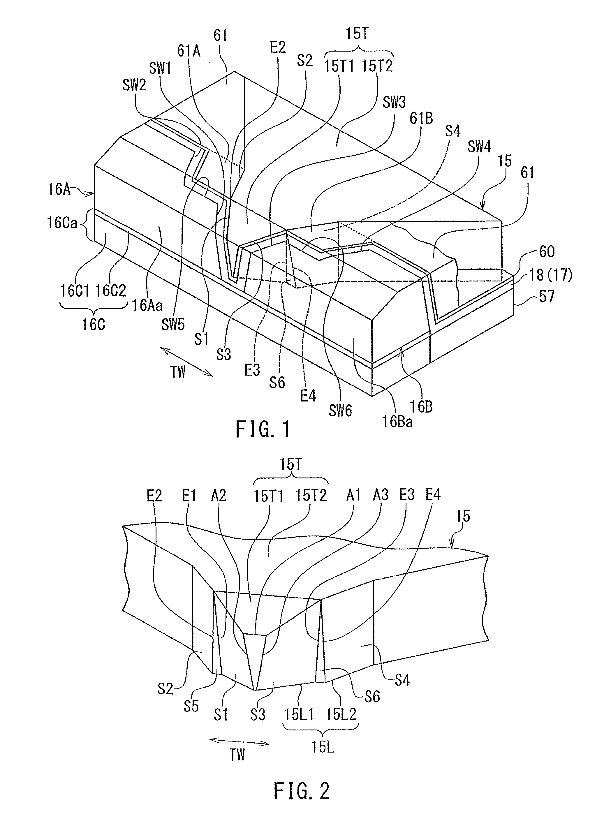
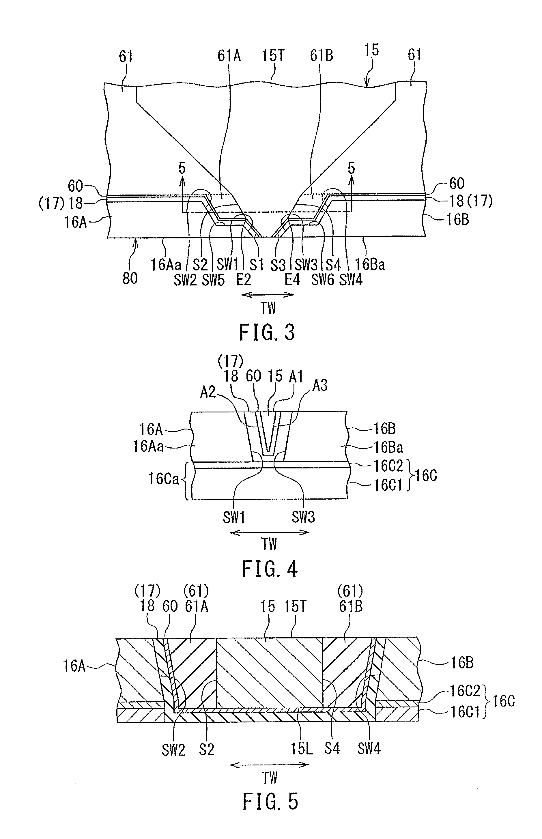
[0059]Preferred embodiments of the present invention will now be described in detail with reference to the drawings. First, reference is made to FIG. 6 to FIG. 10 to describe the configuration of a magnetic head according to a first embodiment of the invention. FIG. 6 is a cross-sectional view showing the configuration of the magnetic head according to the present embodiment. FIG. 6 shows a cross section perpendicular to the medium facing surface and to the top surface of the substrate. The arrow with the symbol T in FIG. 6 indicates the direction of travel of a recording medium. FIG. 7 is a front view showing the medium facing surface of the magnetic head according to the present embodiment. FIG. 8 is a plan view showing a first portion of a coil of the magnetic head according to the present embodiment. FIG. 9 is a plan view showing a first layer of a second portion of the coil of the magnetic head according to the present embodiment. FIG. 10 is a plan view showing a second layer o...

second embodiment

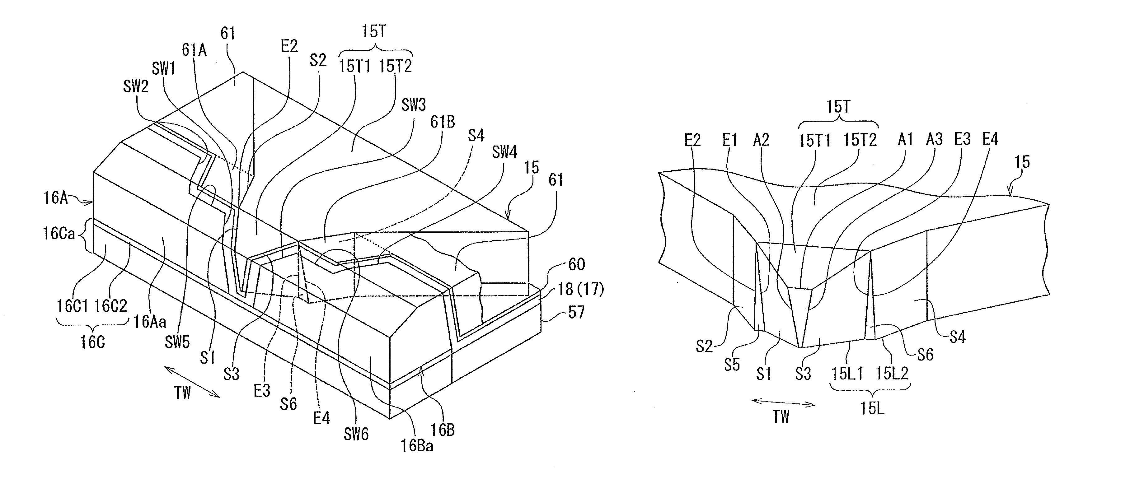
[0164]A magnetic head according to a second embodiment of the invention will now be described. First, with reference to FIG. 27 to FIG. 30, a description will be given of the differences of the magnetic head according to the present embodiment from the magnetic head according to the first embodiment. FIG. 27 is a perspective view of the main pole and the two side shields of the present embodiment in the area near the medium facing surface. FIG. 28 is a perspective view of the main pole of the present embodiment in the area near the medium facing surface. FIG. 29 is a plan view of the main pole and the two side shields of the present embodiment in the area near the medium facing surface. FIG. 30 is a cross-sectional view showing cross sections of the main pole and the two side shields taken along line 30-30 of FIG. 29.

[0165]In the present embodiment, the main pole 15 differs in shape when compared with the first embodiment. As shown in FIG. 27 to FIG. 29, the second and fourth side s...


PUM

PropertyMeasurementUnit
distanceaaaaaaaaaa
thicknessaaaaaaaaaa
thicknessaaaaaaaaaa

Abstract

A main pole has an end face located in a medium facing surface, and first through sixth side surfaces. The first and third side surfaces are connected to the end face of the main pole. The second and fourth side surfaces are located farther from the medium facing surface than are the first and third side surfaces. The fifth side surface connects the first side surface to the second side surface. The sixth side surface connects the third side surface to the fourth side surface. The distance between the first side surface and the third side surface decreases with increasing proximity to the top surface of the substrate. The shape of the first side surface is defined by a first side shield. The shape of the third side surface is defined by a second side shield.

Description

BACKGROUND OF THE INVENTION[0001]1. Field of the Invention[0002]The present invention relates to a magnetic head for perpendicular magnetic recording that is used for writing data on a recording medium by means of a perpendicular magnetic recording system, and more specifically, to a magnetic head for perpendicular magnetic recording that has two side shields.[0003]2. Description of the Related Art[0004]The recording systems of magnetic read / write apparatuses include a longitudinal magnetic recording system wherein signals are magnetized in a direction along the plane of a recording medium (the longitudinal direction) and a perpendicular magnetic recording system wherein signals are magnetized in a direction perpendicular to the plane of a recording medium. It is known that the perpendicular magnetic recording system is harder to be affected by thermal fluctuation of the recording medium and capable of providing higher linear recording density when compared with the longitudinal mag...

Claims


Application Information

Patent Timeline
Patent Type & Authority Patents(United States)
IPC IPC(8): G11B5/147G11B5/187
CPCG11B5/1278G11B5/187G11B5/147G11B5/315
Inventor SASAKI, YOSHITAKAITO, HIROYUKISATO, KAZUKIYASUDA, KAZUMASASHIMIZU, TATSUYA
Owner HEADWAY TECH INC
Why Eureka
Try Eureka