
Device for closing off an opening made in a structural element comprising synchronization, and corresponding automobile

a technology of synchronization and openings, applied in the field of openings, can solve the problems of many relative drawbacks, interesting techniques are difficult to implement on an industrial scale, and can be used for manual flush openings, arching of mobile panels, or even a complete jamming of these mobile panels

Active Publication Date: 2014-07-08
ADVANCED COMFORT SYST FRANCE ACS
View PDF45 Cites 15 Cited by
  • Summary
  • Abstract
  • Description
  • Claims
  • Application Information

AI Technical Summary

Benefits of technology

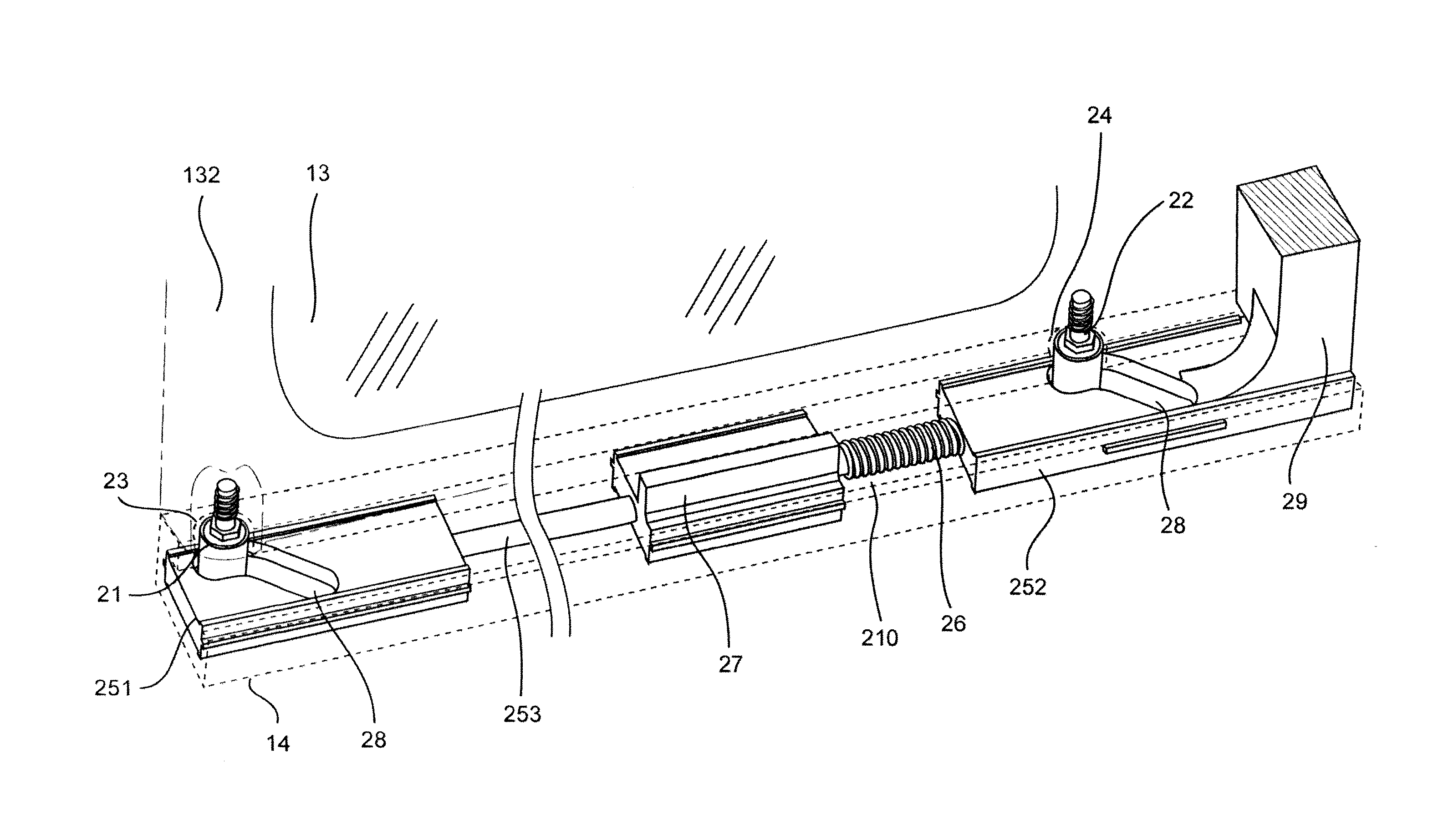
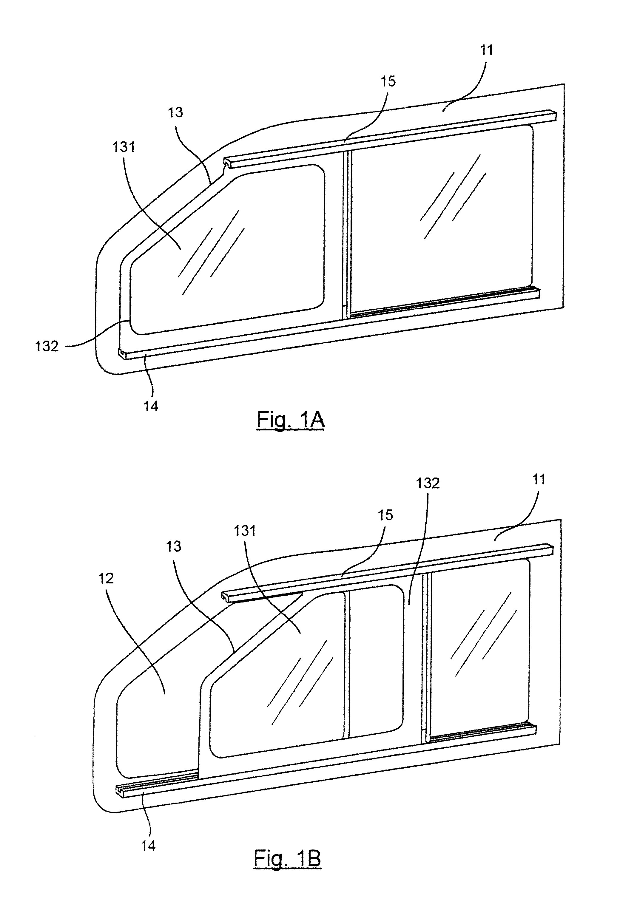
[0034]This approach provides for simple and efficient assembly, with a rail that may be of a reduced dimension and is essentially rectilinear (the shuttle moves substantially rectilinearly in the rail or in the same direction as the rail, and the movement of opening / closing or changing of plane is achieved by the cooperation between the pegs, the shuttles and the rail).
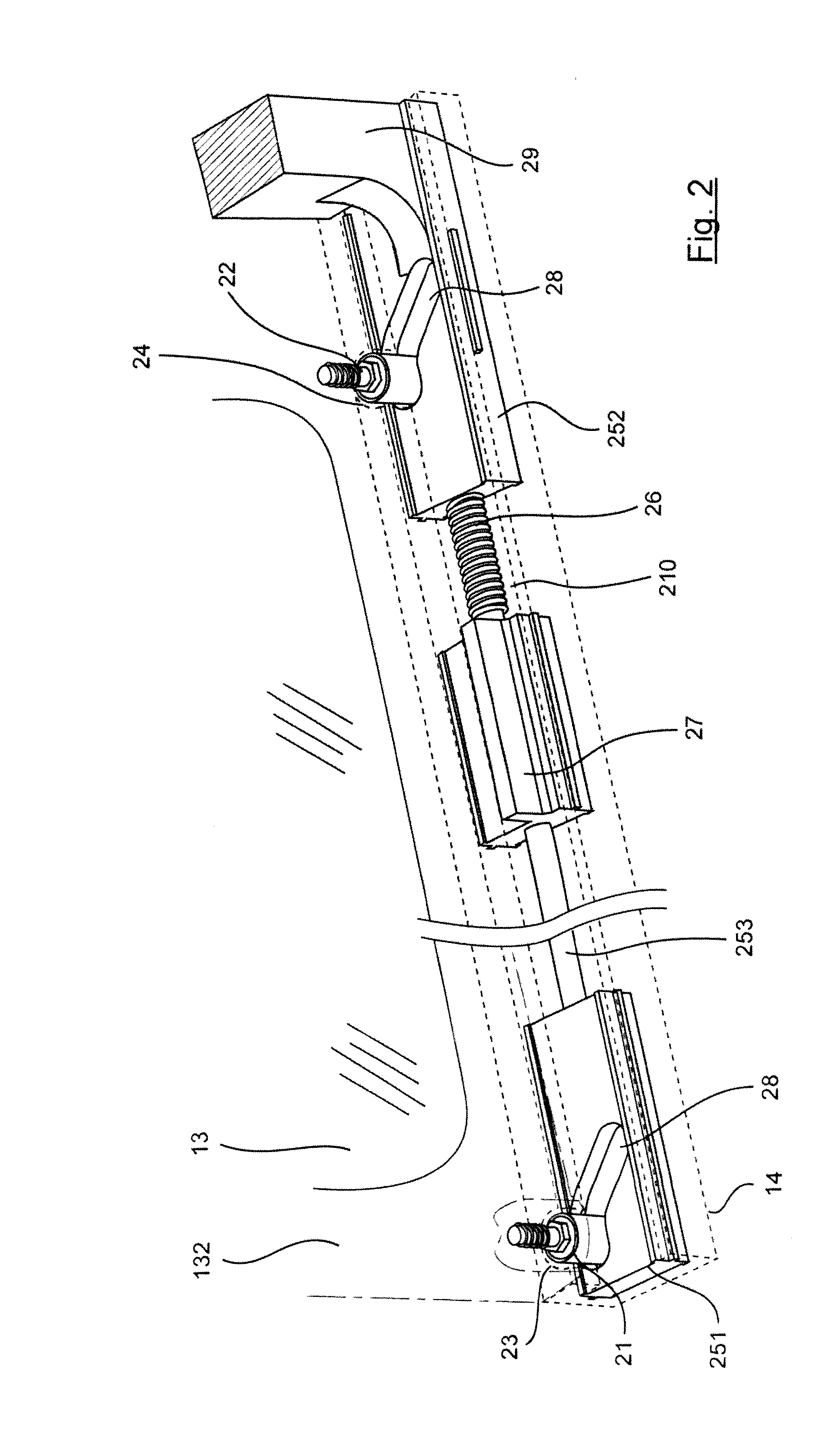
[0037]Thus, a synchronized moving of the shuttles is obtained, for example by applying identical forces, or at least forces that are sufficiently similar, on both shuttles, and the arching and jamming of the sliding panels in the rails is avoided, even in the presence of relatively large clearance values.
[0038]As shall be seen here below, this enables the sliding panel to be actuated efficiently, manually or being motor-driven, without calling for any particular placing or central handling of the handle.
[0045]This element or these elements, depending on their assembly, enable efficient and simple checks on the synchronization of the forces between two shuttles and prevent arching.
[0060]According to certain modes of implementation, said means for actuating comprise electrical or pneumatic drive means, for example, at least one electrical motor or at least one pneumatic actuator. It must be noted that the structure of an embodiment of the invention makes it possible, starting from a same basis, to provide manual openings or motor-driven openings without any complex modification or adaptation.

Problems solved by technology

This technique however has many relative drawbacks, especially with respect to problems of sealing and / or in terms of aesthetics.
This interesting technique proves however to be difficult to implement on an industrial scale both for manual flush openings and for motor-driven (also called electrical) flush openings.
When the actuation is off-centered, the forces applied to each shuttle are different, thus leading to an arching of the mobile panel or even to a complete jamming of this mobile panel.
However, it is not easy to verify whether the user has made a centered actuation, especially for a handle as described in the document PCT / EP2008 / 067264, already referred to, that extends throughout the height of the sliding panel.
This risk of strain is reinforced by the major tolerance values dictated in the automobile field, which do not allow any fine adjustment of each opening but on the contrary require clearances of several millimeters.
In these many embodiments, it is also necessary that the guide rails of the mobile panel should not be parallel, thus adding further strain and further increasing this risk of arching.
The problem is similar in the case of electrical flush openings.
The force provided to the lower shuttle, as proposed in the document PCT / EP2008 / 067264 risks being different from the one applied to the upper shuttle through the crossbeam, which may lead to arching and / or jamming.
Consequently, the manufacture of these openings and their integration into the vehicle are generally complex and costly.
Another drawback of this prior-art technique is that it makes it necessary, especially in a manual implementation, to have a frame and / or a handle that are relatively thick, interfering with transparency in the opening and in certain cases affecting aesthetic quality.

Method used


Image

  • Device for closing off an opening made in a structural element comprising synchronization, and corresponding automobile
  • Device for closing off an opening made in a structural element comprising synchronization, and corresponding automobile
  • Device for closing off an opening made in a structural element comprising synchronization, and corresponding automobile

Examples


first embodiment

3. First Embodiment

3.1 Balancing and Synchronization

[0106]According to a first embodiment of the invention, the balancing means are mounted in the portion of the frame 46 (or in the handle or pullbar 45) as illustrated by FIG. 5. These balancing means enable the synchronization of at least one upper shuttle and at least one lower shuttle (not shown). Should two shuttles be implemented in each rail, the upper shuttles are, in the same way as with the lower shuttles, rigidly linked by a connection bar as described above with reference to FIG. 2.

[0107]The frame portion 46 therefore comprises a balancing and synchronization system comprising two pulleys 51 and 52 (or more generally cable-guiding means) which cooperate with two balancing and synchronization cables 53, 54 crossing each other at the middle of the frame portion 46 (or in the handle or pullbar 45).

[0108]The first cable 53 has a first portion 531 extending along the rail 421 from a first end 5311 up to the pulley 51. This pul...

second embodiment

4. Second Embodiment

[0124]In this second embodiment, illustrated schematically in FIG. 7, there is provided a handle 71 mounted at the lower part of the mobile panel 43 which acts directly on the lower shuttle (not shown). For example, a substantially horizontal pushing action on the handle 71, in the direction of the arrow 73, provides for the moving of the lower shuttle (or in one variant, the moving of the lower shuttles rigidly linked by a connection bar) relatively to the frame.

[0125]Means for synchronizing 74 transmitting an actuation, transmitted to one of the shuttles, to the other one of the shuttles, also called transmission means here below in the description, are provided between the lower shuttle and the upper shuttle (or between the lower shuttles and the upper shuttles), for example in the form of a synchronization cable circulating in the frame 75 of the mobile panel 72.

[0126]The synchronization cable 74 can especially be a push-pull, to-and-fro cable or a leaf sprin...

third embodiment

6. Third Embodiment

[0142]Referring to FIG. 13, we present a third embodiment in which the handle acts directly on the means of synchronization of the shuttles.

[0143]FIG. 13, which is a partial view of the flush opening, shows that the actuating handle 1301 is mounted on a synchronizing leaf spring 1302 substantially at equal distance from the two shuttles 1303A and 1304A which are rigidly connected by a connecting bar to the shuttles 1303B and 1304B respectively. In one variant of this embodiment, it can also be planned to mount the handle between two leaf springs fixed respectively to either of the shuttles. It can also be planned that the synchronization leaf spring 1302 will not be at equal distance from the two shuttles 1303A and 1304A.

[0144]When this handle 1301 is pulled frontward, in the sense of the arrow 1306, it slides horizontally relatively to the frame 1305 (shown in this figure in dashed lines), synchronously driving the upper portion 1307 and the lower portion 1308 of...


PUM


Abstract

A device is provided for sealing an opening made in a structure, including a fixed panel in which an opening is defined, and at least one sliding panel, including: two shuttles respectively guided in two guiding rails mounted and / or formed on the surface of the fixed panel facing the inside of the vehicle and a frame supporting at least two guiding pins respectively engaging with each one of the shuttles. The shuttles include guides for guiding the pins, enabling a transverse movement of the frame relative to the shuttles. An actuator acts directly or indirectly on the shuttles in order to move the latter in the rails, causing the sliding panel to move in a direction perpendicular to the plane of the fixed panel. The device also synchronizes the actuator so as to synchronize the movement of the shuttles.

Description

CROSS-REFERENCE TO RELATED APPLICATIONS[0001]This Application is a Section 371 National Stage Application of International Application No. PCT / EP2010 / 058752, filed Jun. 21, 2010, which is incorporated by reference in its entirety and published as WO 2010 / 146185 on Dec. 23, 2010, not in English.STATEMENT REGARDING FEDERALLY SPONSORED RESEARCH OR DEVELOPMENT[0002]None.THE NAMES OF PARTIES TO A JOINT RESEARCH AGREEMENT[0003]None.FIELD OF THE DISCLOSURE[0004]The field of the disclosure is that of the openings (or bays) used especially in motor vehicles. More specifically, the disclosure relates to devices for closing off an opening prepared in a structural element, for example in the bodywork of a vehicle or in a door of the vehicle, and comprising a sliding mobile part capable of releasing or closing an aperture, in presenting a flush aspect when seen from the exterior. Such devices which have been developed for many years by the holder of the present application, are known for example...

Claims


Application Information

Patent Timeline
Patent Type & Authority Patents(United States)
IPC IPC(8): E05F11/53
CPCB60J1/16
Inventor MALTAVERNE, GUYGERBEAU, SERGEGIRET, FREDERICDESBOIS, MICKAEL
Owner ADVANCED COMFORT SYST FRANCE ACS
Learn More