Sheet hole punching device

a hole punching and sheet technology, applied in the field of hole punching devices and finishing apparatuses, can solve problems such as punching holes in sheets, and achieve the effect of not increasing loads

Active Publication Date: 2014-07-08
SEIKO CORP
View PDF15 Cites 4 Cited by
  • Summary
  • Abstract
  • Description
  • Claims
  • Application Information

AI Technical Summary

Benefits of technology

[0013]The present invention provides a hole-punching method and hole-punching device that can store large volumes of paper cutting debris without the paper cutting debris entering the device, and without increased loads on the hole-punching blades, when punching holes in sheets such as with punch members.
[0014]The present invention further provides a hole-punching device that can punch holes at high speed without reduced shear load when punching holes and at the same time can be configured with a compact and lightweight drive mechanism.
[0017]Further, the above mentioned second problem accomplishes reduction of punching load by moving the punching members (punching action) in the punching direction as rotating the punching members. The hole punching blades are then structured in inclination so that punching holes in the sheets continuously back and forth is reciprocally reversed. The life of the hole punching blades may be thereby lengthened.

Problems solved by technology

The above mentioned first problem is to punch holes in the sheets by moving the punching members in the punching direction as rotating them by reciprocal rotation of the drive motor.

Method used


Image

  • Sheet hole punching device
  • Sheet hole punching device
  • Sheet hole punching device

Examples


first embodiment

[0033][First Embodiment]

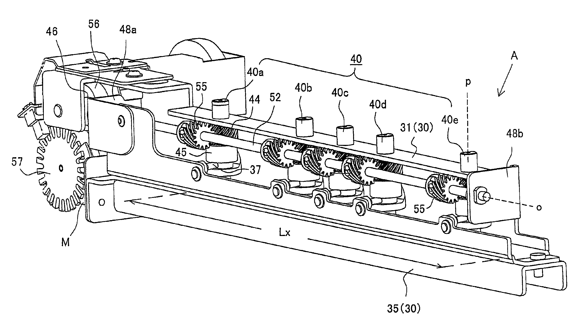
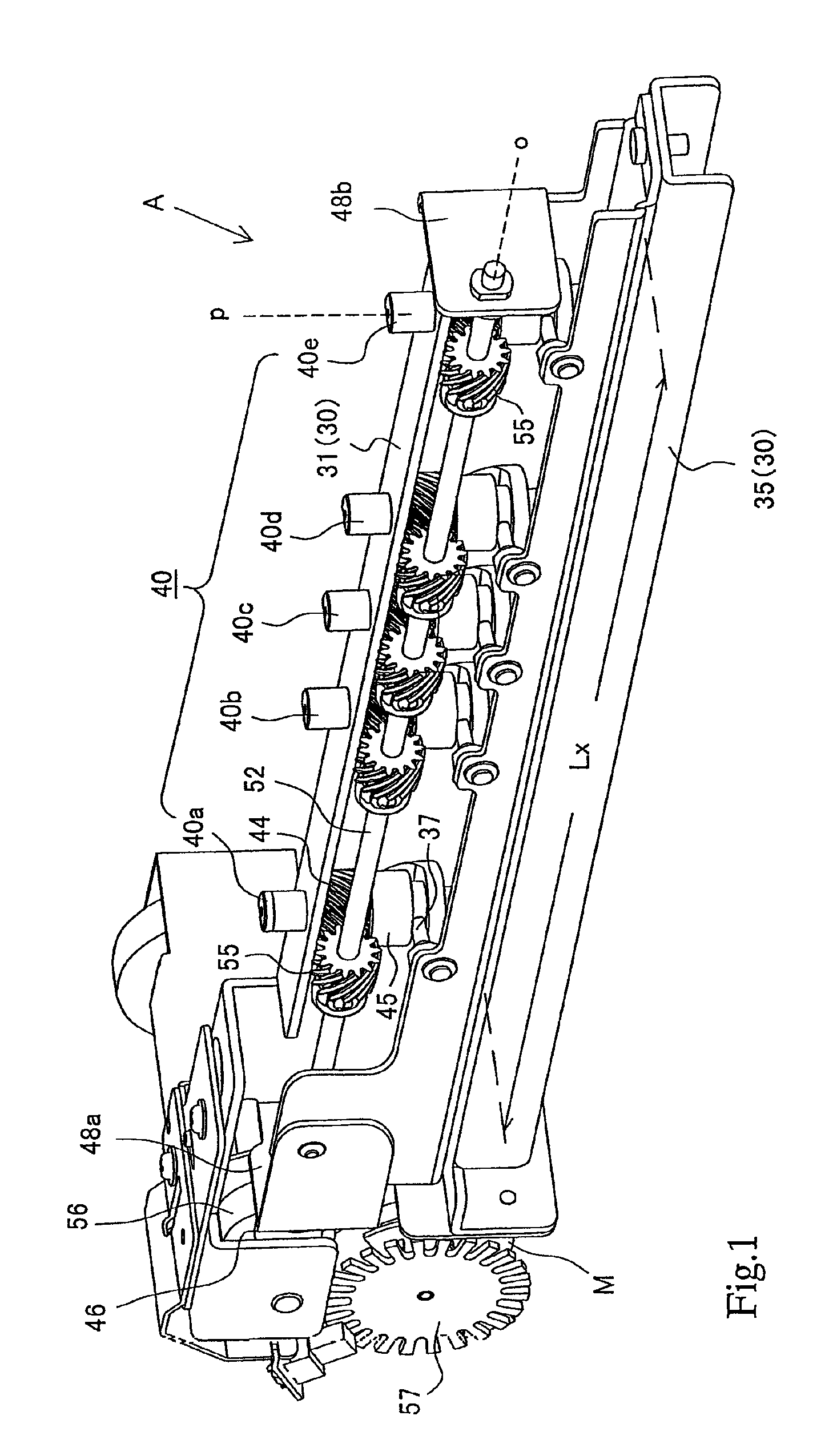
[0034]The sheet hole punching device A in FIG. 1 shows the device structure for punching 2 or 3 holes selectively in the sheets. The sheet hole punching device A is structured with a device frame 30, punching members 40 and a drive means 50.

[0035]The device frame 30 is composed with a sheet placing frame 35 and a base frame 31 having the punching members 40. The sheet placing frame 35 is formed to be longer than a sheet width (length crossing with a sheet transferring direction) Lx because placing the sheets.

[0036]The sheet placing frame 35 is provided with dice (blade-bearing holes) 38 at positions opposite to later mentioned the punching members 40. Under the sheet placing frame 35, debris boxes 33 are placed to receive paper cutting debris dropping from the dices 38.

[0037]A base frame 31 is placed above a space Sd formed in relation with the sheet placing frame 35 for inserting the sheets. In short, the sheet inserting space Sd is formed, and the sheet pla...

second embodiment

[0072][Second Embodiment]

[0073]With respect to the driving gear 70 and the receiving 75 shown in FIG. 11, the driving gear 70 is structure with the worm gear and the receiving gear 75 is structured with the worm wheel. Although not illustrating, other driving gears and receiving gears may be structured with hypoid gears.

[0074][Cam Mechanism]

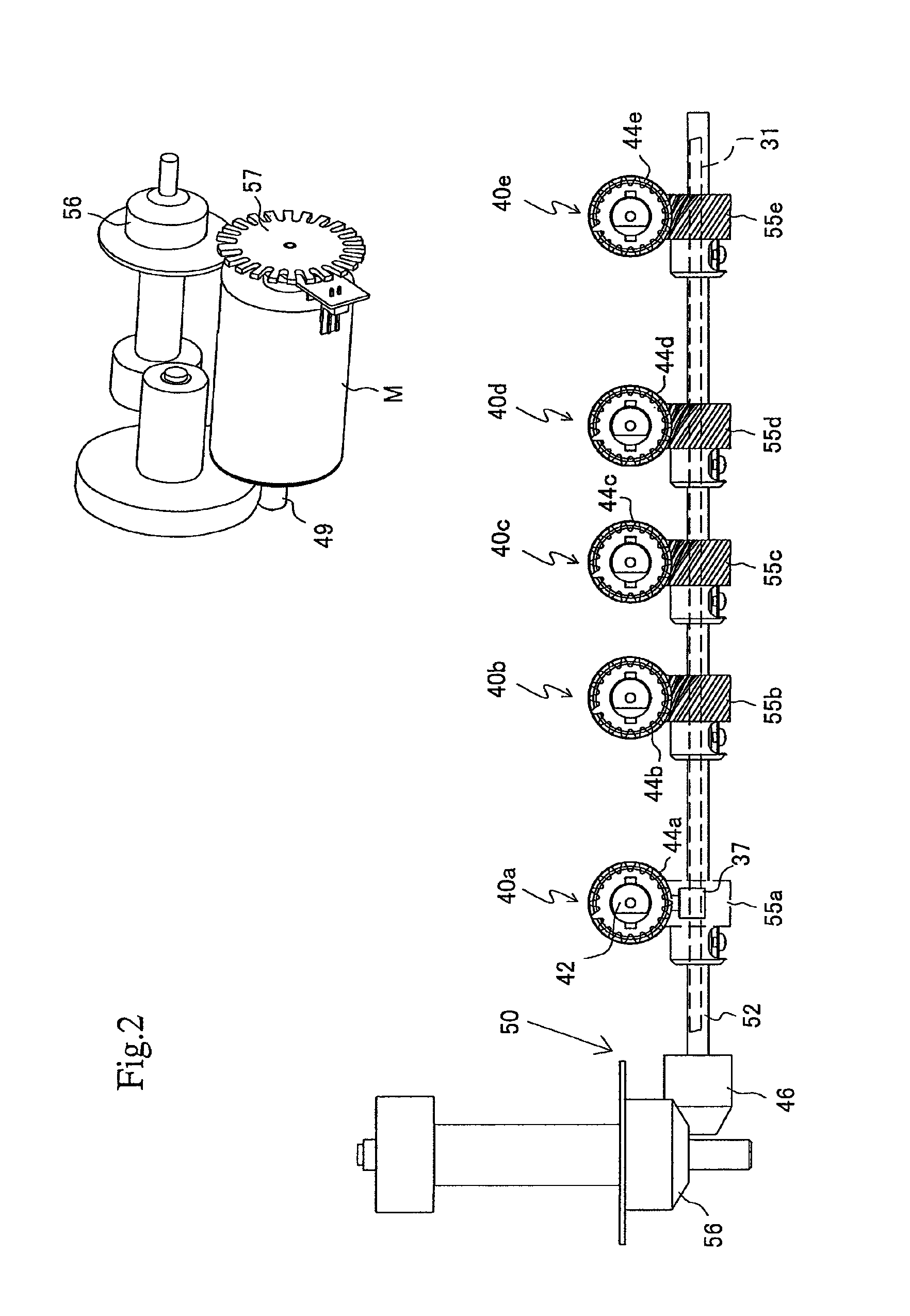
[0075]The cam mechanism shown in FIG. 3 will be explained. Each of the punching members 40a to 40e is furnished with a cylindrical cam (cam means) 45 between the punching member 40 and the base frame 31 for changing rotational movement of the punching member to rotation and movement exerting in the punching direction.

[0076]The cylindrical cam 45 is disposed between the punching member 40 and the base frame 31 for changing rotation movement of the punching member 40 to moving in the punching direction (vertical directions in FIG. 3) simultaneously with rotation.

[0077]Therefore, one of the punching member 40 and the base frame 31 is provided with a...


PUM

PropertyMeasurementUnit
angleaaaaaaaaaa
twist anglesaaaaaaaaaa
screwing angleaaaaaaaaaa

Abstract

A sheet hole punching device has a device frame bearing-supporting a plurality of punching members, a driving rotation shaft, a drive motor, a gear mechanism transmitting a rotation of the driving rotation shaft, cam mechanisms converting the rotational movement into vertical movement, and a motor control device. The gearing mechanism includes drive gears fixed on the driving rotation shaft and receiving gears to engage with the drive gears to transmit the rotational movement to the punching members. The cam mechanism includes cylindrical cams formed integrally to the punching members and cam followers fixed to the device frame. The cylindrical cams are provided with V-shaped groove cams to reciprocate the punching members between an upper dead point and a lower dead point. The punching members are rotated in one direction to punch holes in a sheet, and subsequently rotated in a reverse direction to punch holes in a following sheet.

Description

CROSS-REFERENCE TO RELATED APPLICATIONS[0001]The present application is a continuation-in-part application of Ser. No. 12 / 923,464, filed on Sep. 23, 2010, which is a divisional application of Ser. No. 11 / 727,940, now U.S. Pat. No. 7,823,494.BACKGROUND OF THE INVENTION[0002]1. Field of the Invention[0003]The present invention relates to hole punching methods, hole punching devices and finishing apparatuses, such as those used in conjunction with image forming apparatuses, that punch holes in sheets conveyed out from an image forming apparatus such as a copier, printing machine or printer and the like.[0004]2. Description of Related Arts[0005]Generally, hole-punching devices that punch holes in sheets by manually pushing hole-punching members downward into a plurality of sheets, and automatic hole-punching devices that punch holes in sheets conveyed out of a printing machine or copier are well known as office devices for punching holes in sheets, such as paper, for filing. The former ...

Claims


Application Information

Patent Timeline
Patent Type & Authority Patents(United States)
IPC IPC(8): B26F1/04
CPCB26D7/1818G03G15/6582B26F1/04G03G2215/00818Y10T408/858B26F1/14Y10T83/943Y10T83/8843B26D5/16B26F1/16Y10T83/8828
Inventor BABA, KENJIHASEBE, YUJI
Owner SEIKO CORP
Why Eureka
Try Eureka