Dual mode fiber optic cable system for underwater remotely operated vehicle

a remote-operated vehicle and fiber optic cable technology, applied in special-purpose vessels, instruments, force/torque/work measurement apparatus, etc., can solve problems such as cable failure, and achieve the effects of reducing drag, high strength, and minimizing circumferen

Active Publication Date: 2014-07-08
GENERAL DYNAMICS MISSION SYST INC
View PDF7 Cites 7 Cited by
  • Summary
  • Abstract
  • Description
  • Claims
  • Application Information

AI Technical Summary

Benefits of technology

[0005]In order to minimize the drag, the circumference can be minimized by using a cable that only includes an optical fiber which can be used to transmit data between a batter powered ROV and the support ship. The optical fiber can be encased in a plastic sheath that is surrounded by a high strength Kevlar sleeve. The cable can also include an abrasion resistant external coating which can be made of a high strength elastic material such as urethane. By reducing the circumference, the cable drag can be reduced proportionally. For example, an optical fiber cable that is about 2.9 mm in diameter can have a circumference of about 6.6 mm and the exposed surface area is the length of the cable in the water times 6.6 mm. In contrast, a cable that includes electrical conductors to provide electrical power to an ROV might be twice the diameter. A 5.8 mm diameter cable has a circumference of 26.4 mm. Because the exposed surface area of the thinner optical fiber cable is significantly thinner, the drag and tension will also be significantly lower. If the drag is inversely proportional to the circumference, the reduction of the diameter by 50% can result in a 75% reduction in the wetted surface area of the cable and a correspondingly significant reduction in hydrodynamic drag on the cable.
[0006]If the cable is exposed to excess tension, the optical fiber can be damaged resulting in cable failure. In order to prevent over tensioning the cable, the ROV can include a system which includes a cable storage unit, a cable tension sensor and a cable release mechanism. If the tension in the cable exceeds a predetermined maximum working tension, the cable tension sensor can detect the excessive tension and cause the cable release mechanism to release some of the cable from the ROV. The cable release can be stopped when the cable tension drops below the maximum force. This intermittent increased tension can be due to water currents, contact with objects or other forces. The thinner cable in combination with the cable release mechanism on the ROV can allow the ROV to travel deeper and farther away from the support ship which can greatly enhance the ability of the ROV to perform the required tasks.

Problems solved by technology

If the cable is exposed to excess tension, the optical fiber can be damaged resulting in cable failure.

Method used


Image

  • Dual mode fiber optic cable system for underwater remotely operated vehicle
  • Dual mode fiber optic cable system for underwater remotely operated vehicle
  • Dual mode fiber optic cable system for underwater remotely operated vehicle

Examples


Embodiment Construction

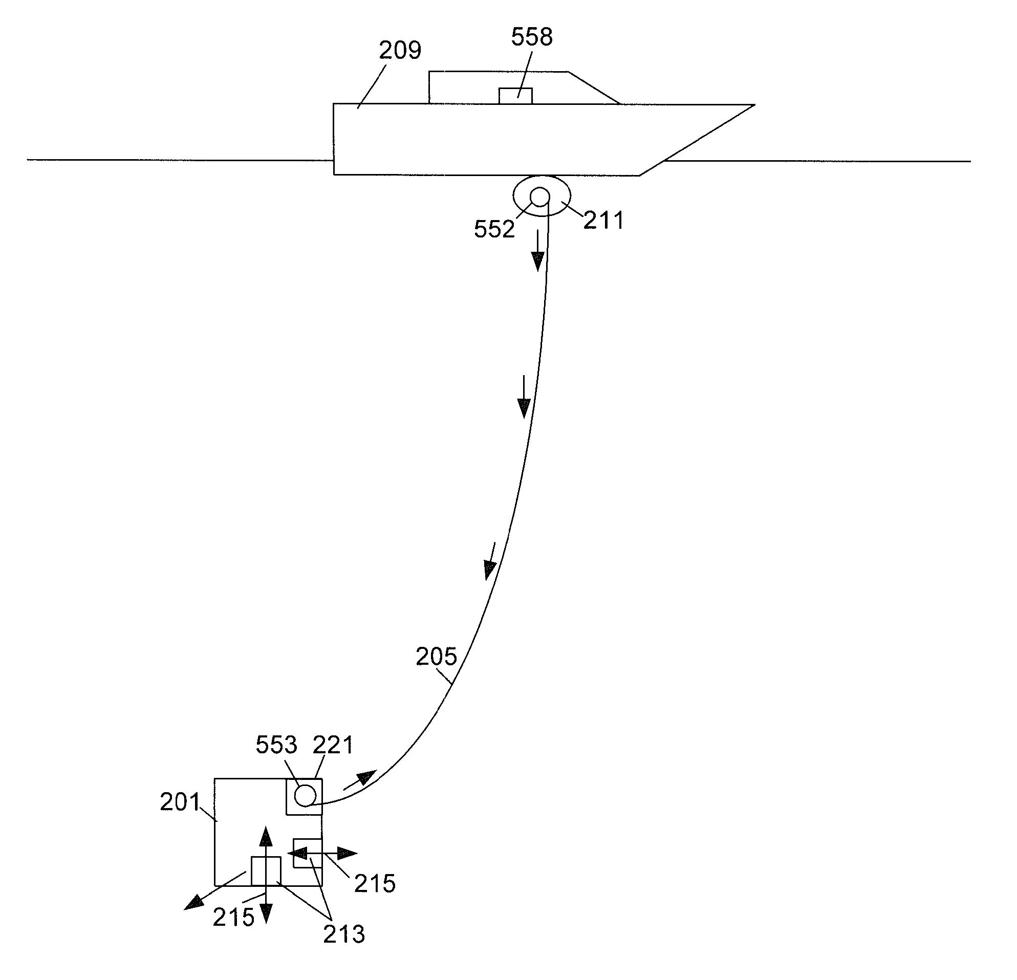
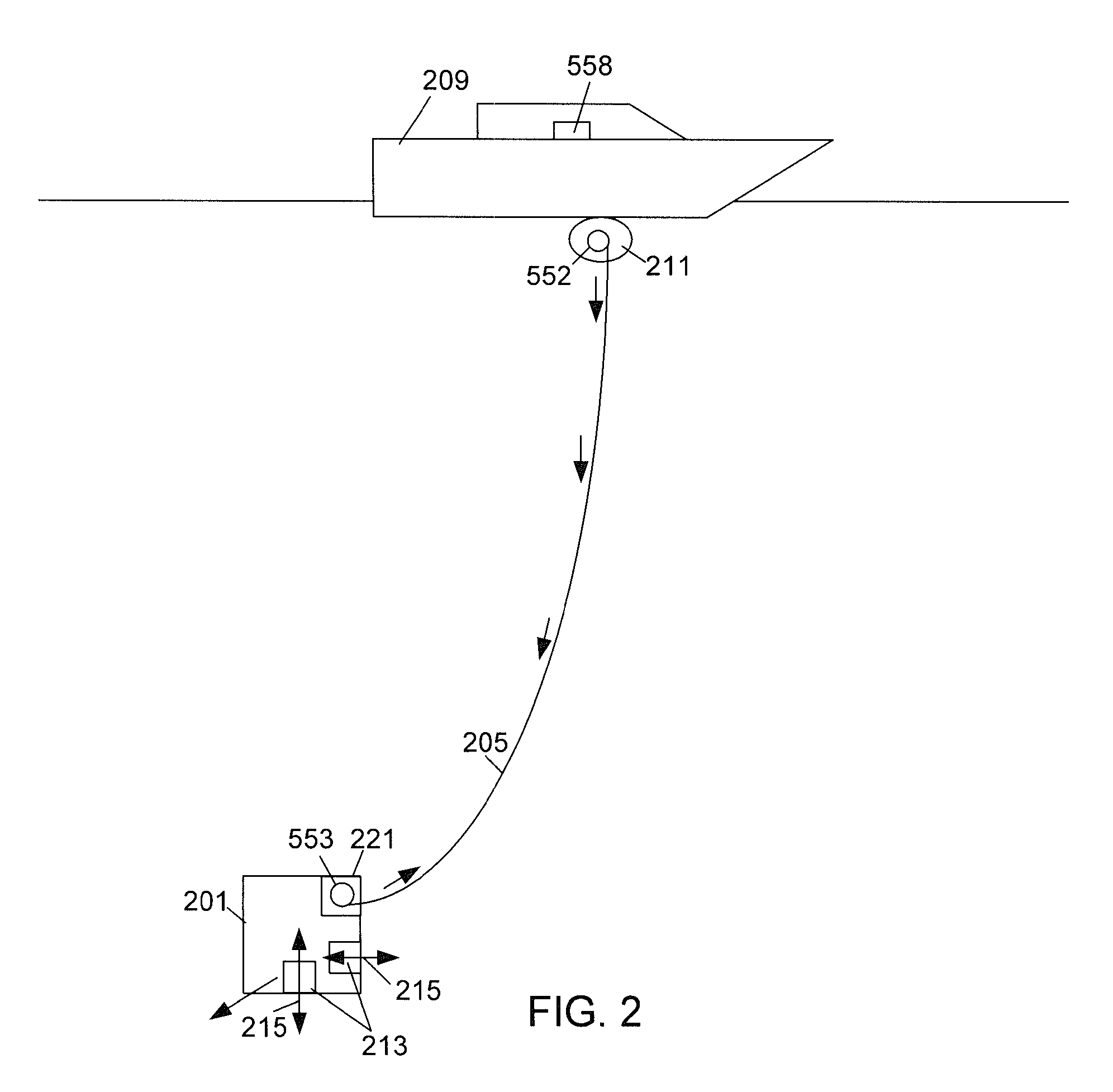
[0015]The present invention is directed towards a system for storing and releasing a cable that extends between an ROV and a support ship from the ROV if the cable tension exceeds a predetermined force to prevent cable failure. This system can be particularly useful for thin cables that include an optical fiber but do not include electrical conductors for powering the ROV. With reference to FIG. 2 a simplified drawing of an ROV 201 is illustrated. The cable 205 can be stored on both a cable storage device 211 on the support vessel 209 as well as in a cable release device 221 on the ROV 201. As the ROV 201 travels away from the support ship 209, the cable 205 is released from the storage device 211. Alternatively, the cable 205 can be stored on the deck of the support ship 209 and can be mechanically or manually released as the ROV 201 travels away from the ship 209.

[0016]During normal operations the cable 205 aboard the ROV 201 can remain in reserve and it may not be used. The ROV 2...


PUM

PropertyMeasurementUnit
lengthaaaaaaaaaa
circumferenceaaaaaaaaaa
diameteraaaaaaaaaa

Abstract

A cable containing an optical fiber is used to transmit data between an underwater remotely operated vehicle (ROV) and a support vessel floating on the surface of the water. The ROV pulls the cable through the water and as the ROV dives away from the support vessel, the optical fiber is released from the support vessel. Excess tension in the cable can damage the optical fiber and the tension can be highest close to the ROV. To prevent potential damage to the optical fiber, the ROV can store a portion of the cable and release the cable if the detected tension approaches the maximum working load. When the tension drops to a lower safe level, the release mechanism can stop releasing the cable.

Description

CROSS REFERENCE TO RELATED APPLICATIONS[0001]This application claims priority to U.S. Provisional Patent Application No. 61 / 500,246, “Dual Mode Fiber Optic Tether For Underwater Remotely Operated Vehicle,” filed Jun. 23, 2011, the entire contents of which are hereby incorporated by reference.BACKGROUND[0002]With reference to FIG. 1, remotely operated underwater vehicles (ROV's) 101 are, widely used by industry and science for unmanned undersea work tasks. Some ROVs 101 require an electromechanical cable connection (tether) 105 to the surface for communications and power which are typically located on a boat 109. These cables 105 are thick and heavy because they contain the required electrical conductors to provide power to the ROV 101. As the ROV 101 moves away from the boat 109, the tether 105 is released from a tether storage device 111.[0003]In order to control the movement, the thrust 115 produced by the propulsion device 113 on the ROV 101 must be greater than the tension in th...

Claims


Application Information

Patent Timeline
Patent Type & Authority Patents(United States)
IPC IPC(8): B63B21/00B63C11/34B63C11/42B65H75/42B65H75/44G01L5/10H02G1/10H02G11/02
CPCB63C11/34B63C11/42B65H75/425B65H75/4484B65H2701/32G01L5/103H02G1/10H02G11/02
Inventor HAWKES, GRAHAMCHIAU, CHARLESWRIGHT, ADAM
Owner GENERAL DYNAMICS MISSION SYST INC
Why Eureka
Try Eureka