Engine cooling system

a cooling system and engine technology, applied in the direction of machines/engines, loading/unloading vehicles, transportation items, etc., can solve the problems of not teaching what to do, reducing visibility for operators using machines,

Active Publication Date: 2014-07-08
CATERPILLAR FOREST PRODS
View PDF35 Cites 133 Cited by
  • Summary
  • Abstract
  • Description
  • Claims
  • Application Information

AI Technical Summary

Problems solved by technology

Such equipment is generally situated in an engine compartment of the machine and takes up a large amount of space in that compartment or requires a larger engine compartment.
However, increasing the size of the engine compartment generally reduces visibility for an operator using the machine.
Unfortunately, the '499 patent does not teach what to do if more than two features (e.g., 1-the supercharger intercooler and 2-the engine radiator) of the vehicle need cooling.

Method used


Image

  • Engine cooling system
  • Engine cooling system
  • Engine cooling system

Examples


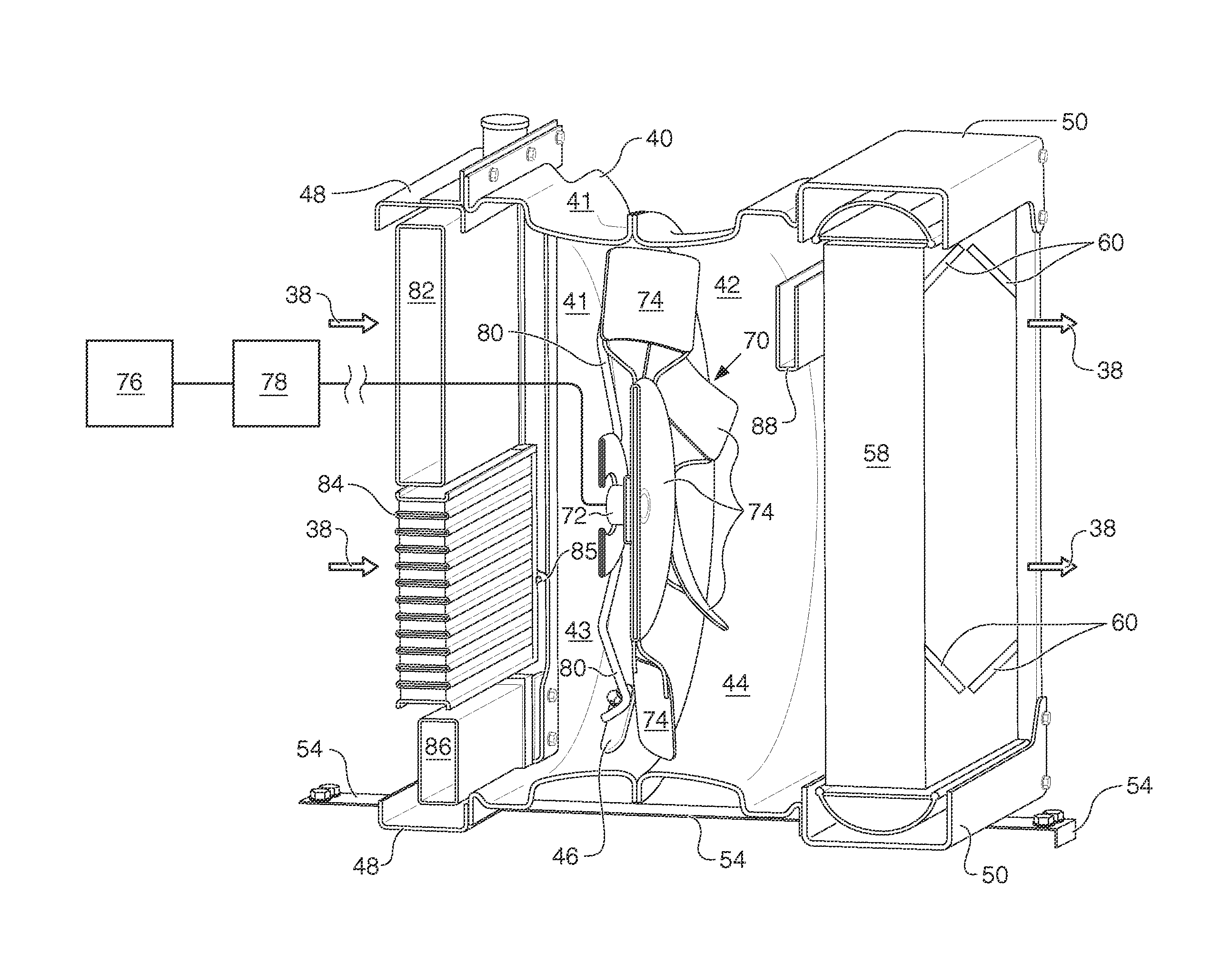
Embodiment Construction

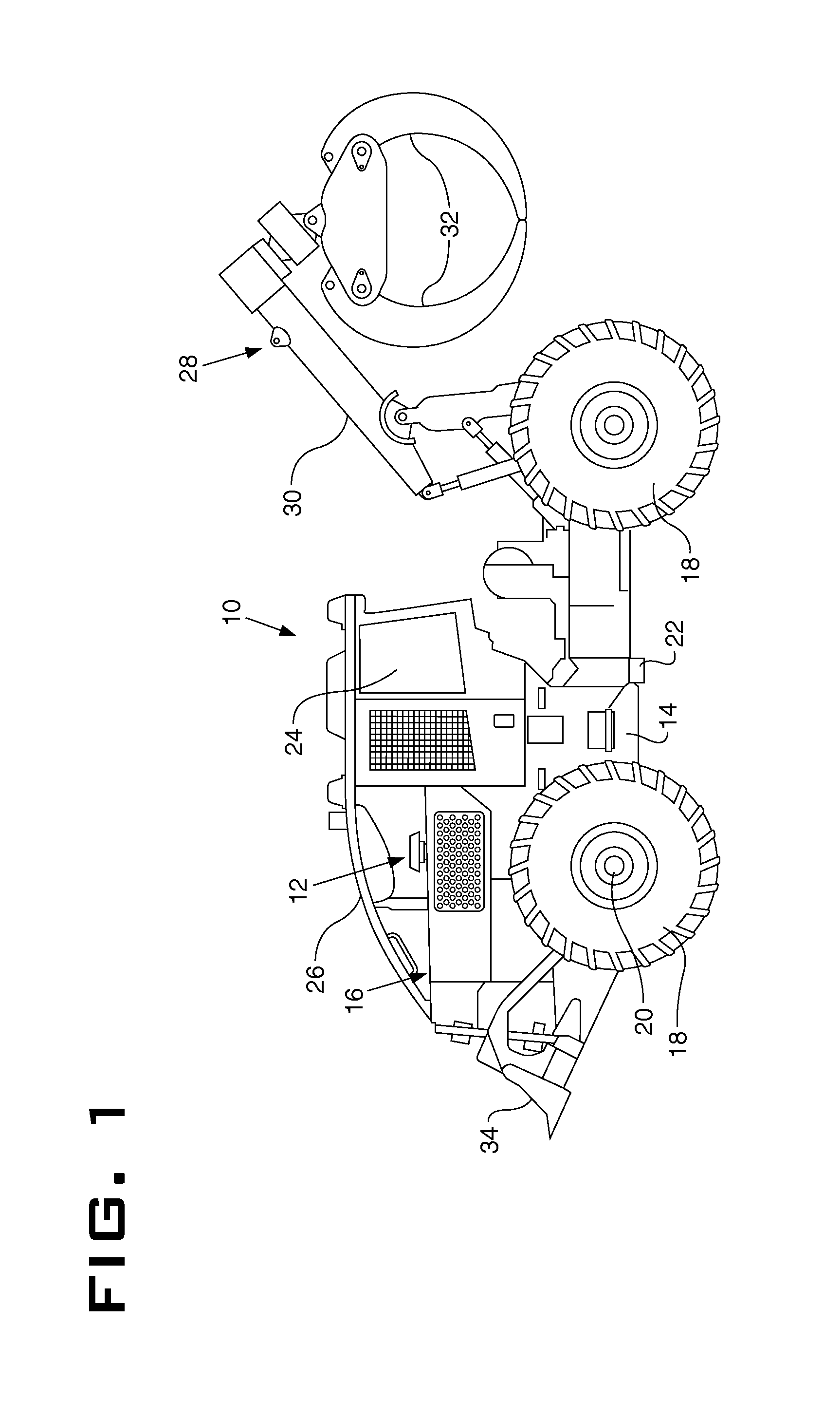
[0013]The present disclosure relates generally to an engine cooling system. In a specific embodiment, the present disclosure relates to a skidder machine having an engine cooling system with an enclosed fan.

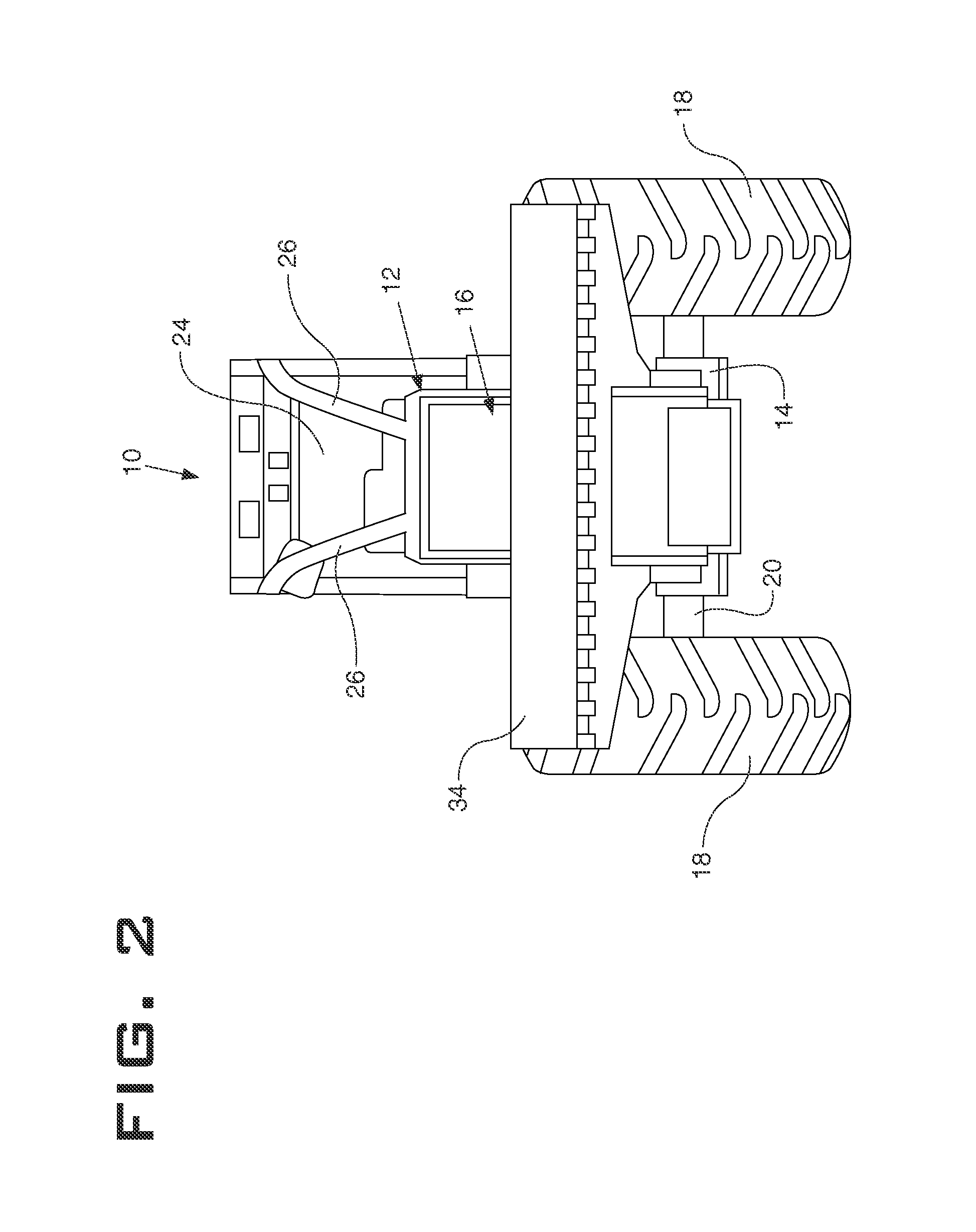
[0014]FIG. 1 illustrates a side view of an embodiment of a skidder machine 10 including an engine cooling system 12 according to the present disclosure. FIG. 2 illustrates a front view of the skidder machine of FIG. 1. While the main embodiments of the present disclosure are described generally for a skidder machine 10, it should be understood that the engine cooling system 12 disclosed herein can be used with engines for other machines (e.g., wheel loaders, track-type tractors, & etc.), vehicles (e.g., cars, trucks, & etc.), industrial engines (e.g., power generating systems, pumping systems, & etc.), locomotives, and anywhere else engine cooling systems are used.

[0015]The skidder machine 10 has a frame 14 supporting an engine 16. The engine 16 is a reciprocating diesel engine. ...


PUM


Abstract

An engine cooling system includes a first heat exchanger receiving a first fluid and a second heat exchanger receiving a second fluid. The second heat exchanger is located adjacent the first heat exchanger, thereby creating a stacked heat exchanger. The engine cooling system also includes a third heat exchanger receiving a third fluid. The third heat exchanger is located apart from the stacked heat exchanger. A venturi is located between the stacked heat exchanger and the third heat exchanger. An air mover is mounted to the venturi and located within the venturi. The air mover is configured to move air through the stacked heat exchanger and through the third heat exchanger. In a specific embodiment, the engine cooling system is incorporated into a vehicle, such as a skidder vehicle.

Description

TECHNICAL FIELD[0001]The present disclosure relates generally to an engine cooling system. In a specific embodiment, the present disclosure relates to a skidder machine having an engine cooling system with an enclosed fan.BACKGROUND[0002]Many types of machines and vehicles use an engine for motive power, and rely upon a radiator and an air circulation fan to assist in cooling the engine. The engine, radiator and fan are typically positioned within a housing that includes an air intake screen and an outlet opening. During normal operations, the fan draws air into the housing through the air intake screen, directs the air through the radiator and out of the housing through the outlet opening.[0003]Legislation mandating a reduction in engine noise, engine emissions, and a variety of other engine byproducts has forced manufacturers of machines and vehicles to develop a host of equipment, such as noise suppressors and clean emission modules, to interface with the engine to comply with th...

Claims


Application Information

Patent Timeline
Patent Type & Authority Patents(United States)
IPC IPC(8): B60K11/04
CPCB60K11/04F01P3/18F01P5/06F01P11/10F01P2003/182F01P2003/187
Inventor SPITLER, JASON
Owner CATERPILLAR FOREST PRODS
Why Eureka
Try Eureka