Bumper

a bumper and bumper technology, applied in the direction of bumpers, vehicle components, vehicular safety arrangments, etc., can solve the problems of plastic deformation or crash of the pair of adjacent portions inside the pair of connecting portions is easily damaged, etc., to prevent the temperature of the targeted portion, the bumper is not damaged, and the product of the present invention is not impaired.

Active Publication Date: 2014-07-08
ASTEER
View PDF10 Cites 3 Cited by
  • Summary
  • Abstract
  • Description
  • Claims
  • Application Information

AI Technical Summary

Benefits of technology

[0012]The reinforcement beam is made of metal, preferably made of a metal plate or metal plates. A strength of whole of the reinforcement beam is enhanced by quenching whole of the reinforcement beam except for unquenched portions. The pair of supporting members may be either a separate members protruding from the vehicle frame or integral members protruding from the vehicle frame as one member. Material of the pair of supporting members is not limited to metals and may be ceramics or plastics as long as the pair of supporting members plastically deforms or crashes to absorb the impact energy. “Connecting portion” means a portion divided by boundaries of a width of the supporting member. “Adjacent portion inside the connecting portion” means an inside portion adjacent to the connecting portion excluding the center region of the reinforcement beam. The unquenched portions may be provided over both of the connecting portion and the adjacent portion inside the connecting portion.
[0013]The unquenched portions are provided on the pair of connecting portions or a pair of adjacent portions inside the pair of connecting portions. The mechanical strength of the unquenched portions is smaller than the mechanical strength of the pair of support members and the quenched region. The unquenched portions more easily plastically deform than the quenched region while undergoing the light collision. This prevents the connecting portions from being pulled by a plastic deformation or crash of portions other than the connecting portions, and prevents supporting member from crashing or inclining.
[0015]In the present invention, the unquenched portions are formed by preventing temperature of targeted portions from rising or by chilling the targeted portions when conducting quenching treatment. The quenching treatment does not include a gradual chilling treatment lasting for long time, which is necessary for an annealing treatment, after heating. Since the bumper of present invention is readily manufactured by forming the unquenched portions when conducting quenching treatment on the reinforcement beam, the productivity of the bumper of present invention is not impaired.
[0016]According to the present invention, the connecting portions of the reinforcement beam or the pair of adjacent portions inside the pair of connecting portions is more easily plastically deform than the quenched region. This prevents the connecting portions from being pulled by a plastic deformation or crash of portions other than the connecting portions and prevents supporting member from bending or inclining. Because the bend or inclination of the supporting member is a cause of reducing the gross energy adsorption amount, the energy adsorption amount is enlarged according to the present invention. The bumper reinforcement beam is prevented from protruding backward and displacing backward in this protruding state.
[0017]According to the present invention, whole of the reinforcement beam and the connecting portions plastically deform or crash differently in the case of the light collision. While undergoing the heavy collision, both of the reinforcement beam and the supporting member plastically deform or crash. The vehicle frame is not influenced by the light collision due to the plastic deformation or crash of the reinforcement beam. With respect to the heavy collision, both of the reinforcement beam and the supporting member to plastically deform or crash to secure gross energy adsorption amount. Also, with respect to the heavy collision, the reinforcement member is prevented from protruding backward and displacing backward in this protruding state. Productivity of the bumper of present invention is excellent.

Problems solved by technology

Because a plane between the corners is easy to be plastically deformed or crashed, if the unquenched portions are provided over the corners sandwiching the plane, the pair of connecting portions or the pair of adjacent portions inside the pair of connecting portions easily plastically deform or crash.

Method used


Image

  • Bumper
  • Bumper
  • Bumper

Examples


Embodiment Construction

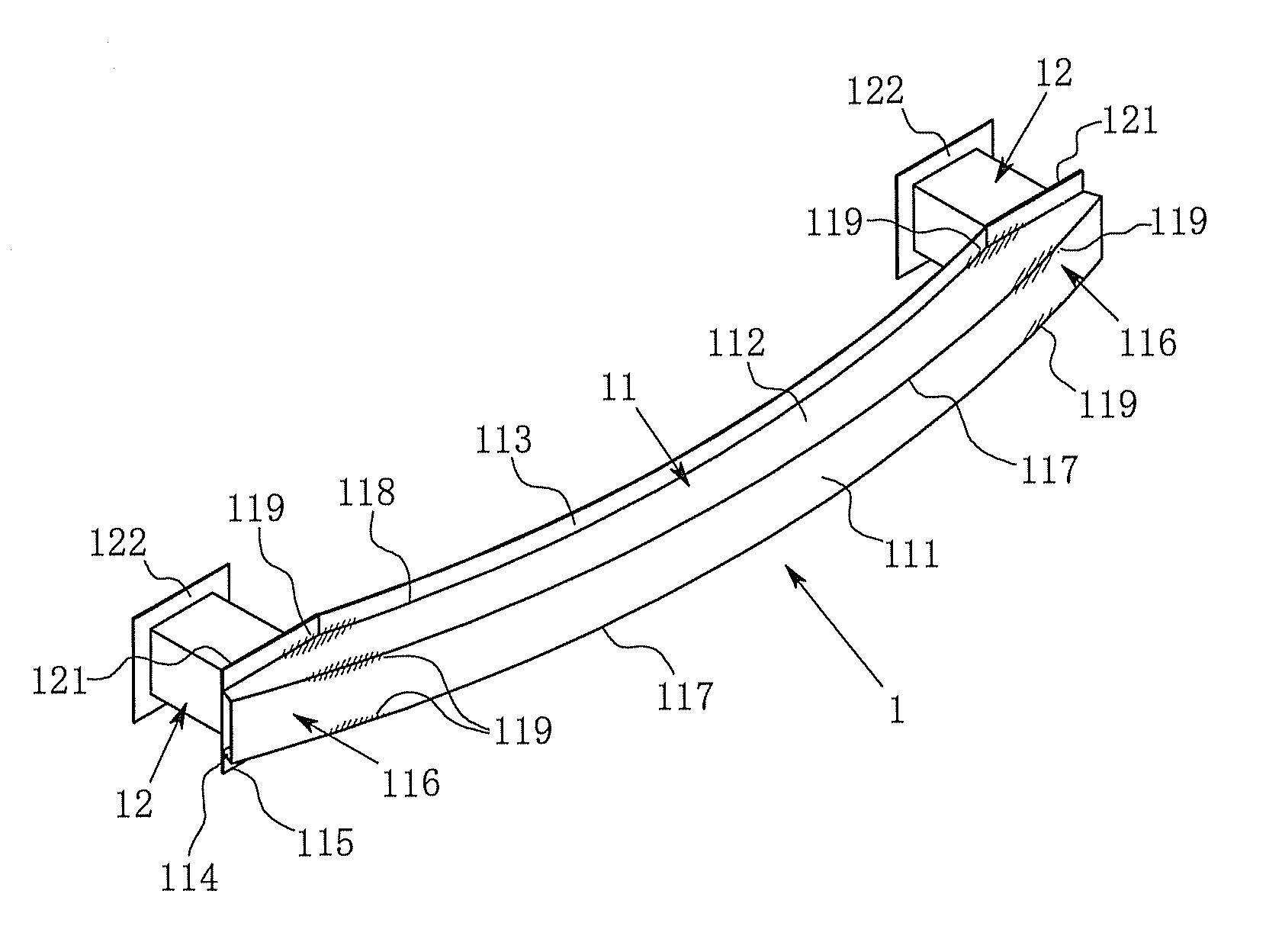
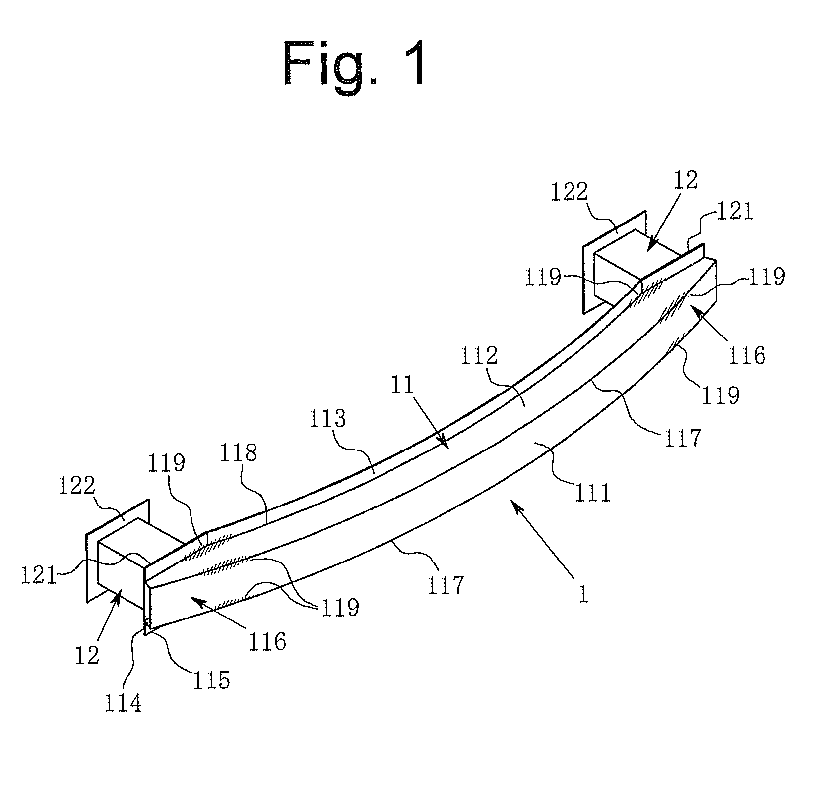
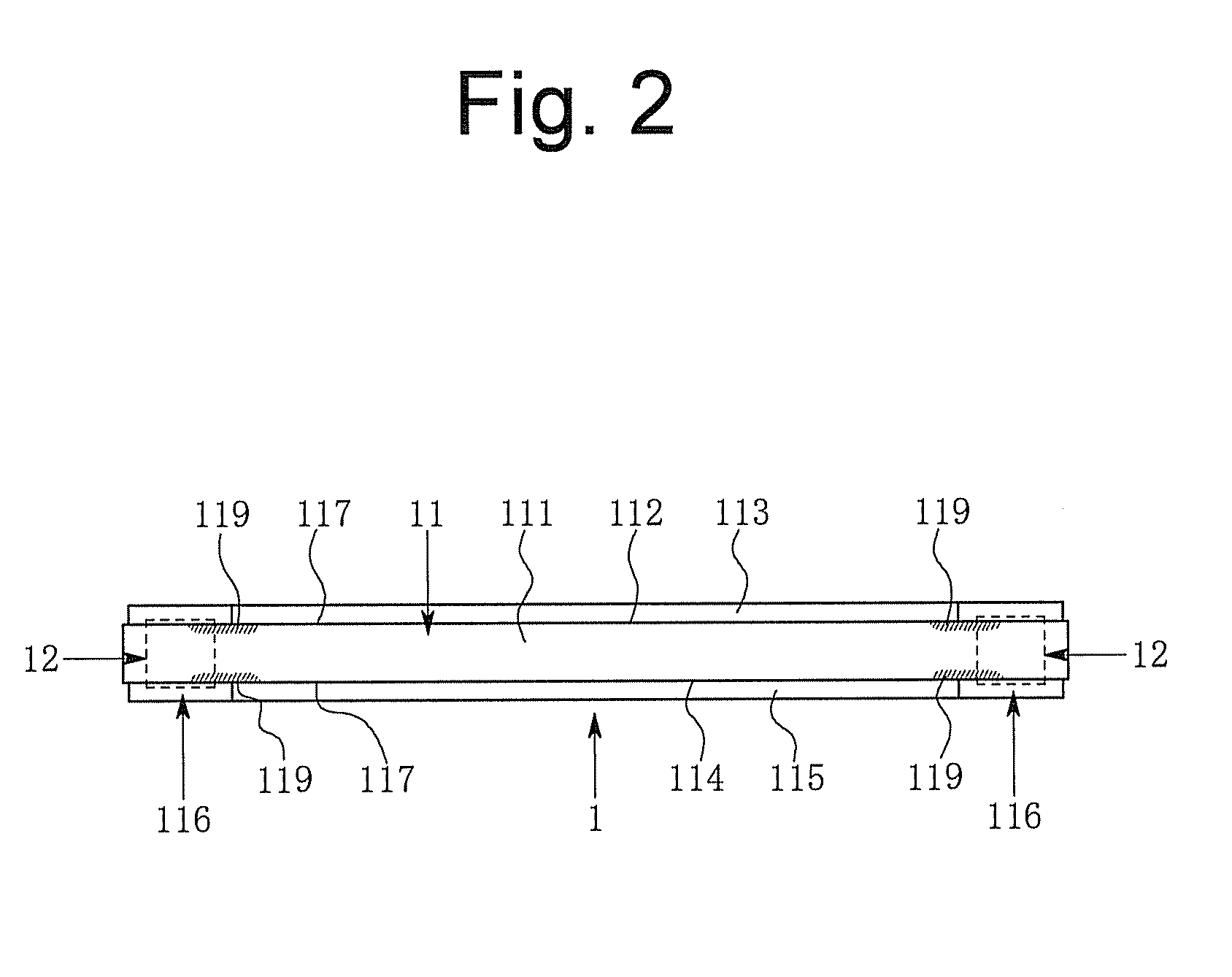
[0026]Preferred embodiment to carry out the present invention is hereinafter explained with reference to Figs. One example of the present invention is illustrated in FIGS. 1 to 5. Bumper 1 of the present example includes; a reinforcement beam 11 made of a steel plate which is totally quenched except for unquenched portions 119; and a pair of support members 12, 12 made of steel plate and protruding from a vehicle frame, which is not illustrated in Figs. The bumper 1 of the present example is connected to the vehicle frame via a pair of connecting flanges 122, 122 provided at back end of the pair of support members 12, 12.

[0027]The reinforcement beam 11 includes a front face 111, an upper face 112 continuing from an upper end of the front face 111, a lower face 114 continuing from a lower end of the front face 111, an upper flange 113 continuing from a back end of the upper face 112 and a lower flange 115 continuing from a back end of the lower face 114. The upper face 112, the upper...


PUM


Abstract

Providing a bumper absorbing large amount of impact energy with respect to both a light collision and a heavy collision, and preventing the reinforcement beam from bending and protruding backward at a portion where an obstacle collides and from displacing backward in this protruding state. Provided is a bumper for vehicles including a reinforcement beam made of metal and a pair of support members having a hollow cross section, protruding from a vehicle frame, and supporting the reinforcement beam therebetween. A quenched region is provide over a portion including a middle of the reinforcement beam. Unquenched portions are provided on the pair of connecting portions or a pair of adjacent portions inside the pair of connecting portions.

Description

BACKGROUND OF THE INVENTION[0001]1. Field of the Invention[0002]The present invention relates to a bumper for vehicles including a reinforcement beam made of metal and a pair of support members having a hollow cross section. The pair of support members protrudes from a vehicle frame and supports the reinforcement beam therebetween.[0003]2. Description of the Related Art[0004]A bumper is, for example, provided at a front end of a vehicle. The bumper absorbs an impact energy when the vehicle collides with an object. A bumper configured by a reinforcement beam which is totally quenched and a pair of supporting members supporting the reinforcement beam therebetween is proposed. This kind of bumpers absorbs the impact energy by plastically deforming or crashing the reinforcement beam or the pair of supporting members. Since a force-stroke curve and a total impact energy absorption amount change in accordance with how the reinforcement beam deforms or crashes, a structure and configuratio...

Claims


Application Information

Patent Timeline
Patent Type & Authority Patents(United States)
IPC IPC(8): B60R19/03
CPCB60R19/18B60R2019/1813
Inventor SHIMOTSU, KOJI
Owner ASTEER
Why Eureka
Try Eureka