Systems and methods for imaging and processing tissue

a tissue imaging and tissue technology, applied in the field of biomedical science for imaging and tissue processing methods, can solve the problems of inability to directly apply organ level imaging, inability to image macroscopic 3d tissues, and limited depth penetration of tpm, so as to achieve rapid image samples with arbitrary thickness, high reliability, and accurate digital registration

Active Publication Date: 2014-07-08
TISSUEVISION
View PDF14 Cites 35 Cited by
  • Summary
  • Abstract
  • Description
  • Claims
  • Application Information

AI Technical Summary

Benefits of technology

[0010]An advantage of this methodology over block face techniques is that any distortions that are introduced by the sectioning procedure do not introduce artifacts in the reconstructed 3D volume since the cut plane is always pre-imaged. Further, imaging of overlapping regions between successive sections ensures accurate digital registration between sections on a pixel by pixel basis. To overcome the limitations in data acquisition speed, two methods of high speed two-photon microscopy can be utilized. To overcome the field of view limitations of the objective, the robotic stage raster scans the sample allowing a larger image to be constructed from a series of overlapping 3D volumes. After the section is removed with the microtoming procedure, the entire sample is translated towards the objective. Unlike with serial section reconstruction, where alignment of successive z-sections is often ambiguous, the integrated precision robotic stage insures high reliability in registering neighboring volumes both in the axial and radial direction. The microscope system is entirely automated and requires no user intervention once the sample has been mounted.

Problems solved by technology

Despite the strengths of traditional TPM, it cannot be directly applied to organ level imaging due to three factors.
First, the depth penetration of TPM is still limited to a few hundred microns for most tissue types, presenting a barrier to imaging tissue or organs which have a substantive axial extent.
Second, the typical field of view of standard TPM has a linear dimension of only a few hundred microns, thus requiring a scanning procedure over an extended period that is impracticable for whole organ imaging.
Third, standard TPM systems have an image acquisition speed that is also prohibitively slow for imaging macroscopic 3D tissues.

Method used


Image

  • Systems and methods for imaging and processing tissue
  • Systems and methods for imaging and processing tissue
  • Systems and methods for imaging and processing tissue

Examples


Embodiment Construction

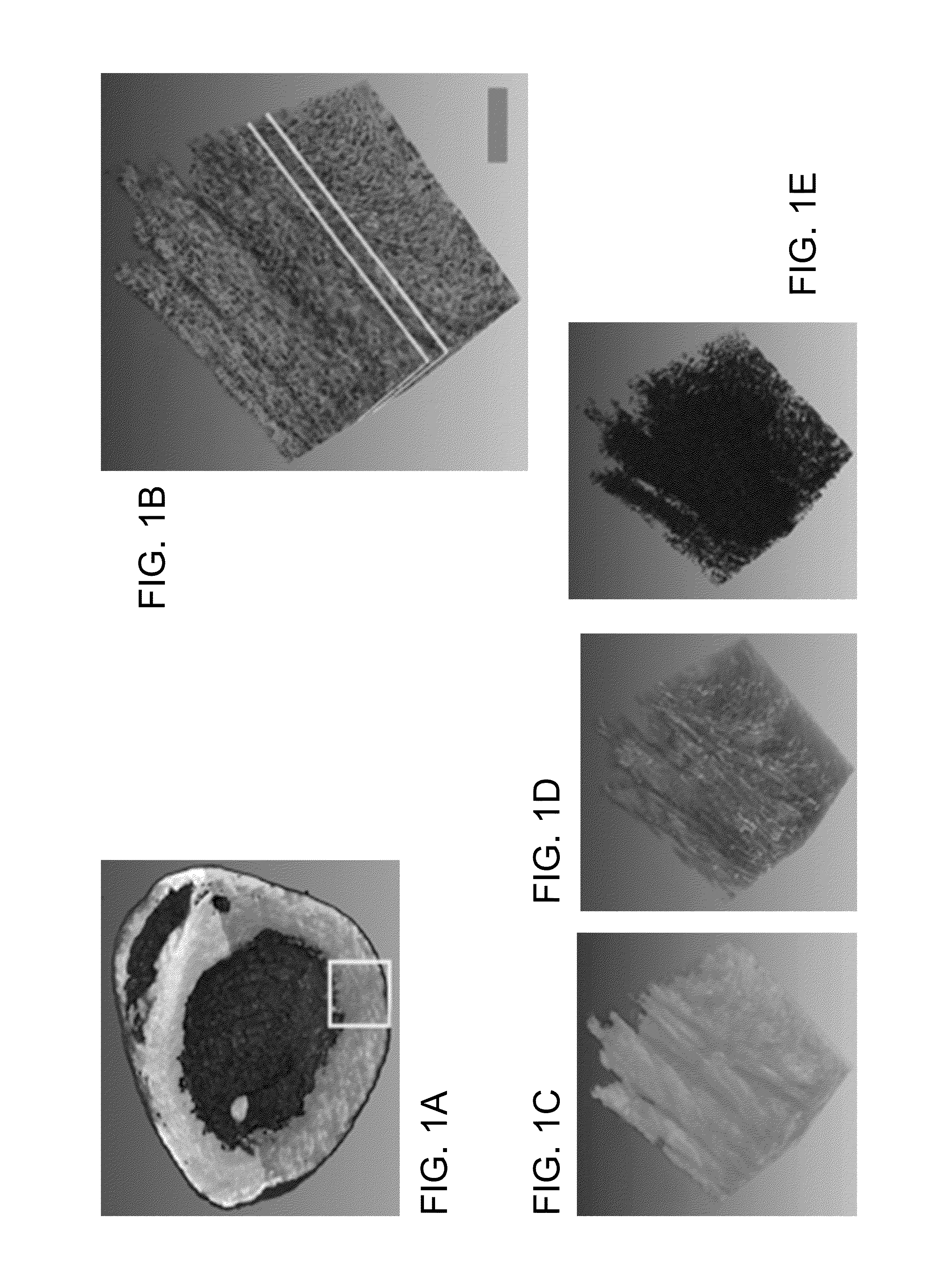
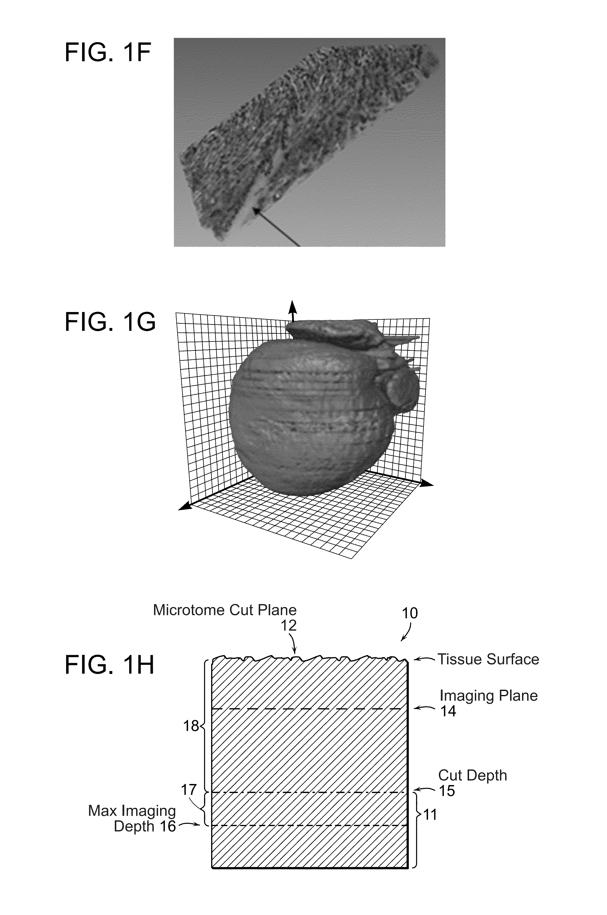
[0031]FIG. 1A-1G illustrates image data that can be acquired and processed in accordance with the invention. An entire mouse heart was imaged with sub micron resolution and multispectral detection as shown in FIG. 1A. This system visualizes details at the subcellular level throughout the entire heart, revealing features of the nuclei, vessel architecture, mesoscale architecture such as cleavage planes in the heart, and the macroscopic morphology of the heart chambers. This entire 3D data can span almost five orders of magnitude. FIG. 1B shows autofluorescence of heart tissue with labeled nuclei and vasculature wherein the scale bar is 100 μm. FIG. 1C shows cleavage planes of laminar sheets of sectional myocardium. FIG. 1D shows morphology of the 3D microvasculature. FIG. 1E shows nuclei from the myocytes, fibroblasts and endothelial cells lining the vasculature. FIG. 1F shows the section outlined in FIG. 1B where the arrow indicates space between successive cleavage planes. FIG. 1G ...


PUM

PropertyMeasurementUnit
thicknessaaaaaaaaaa
depthaaaaaaaaaa
depth penetrationaaaaaaaaaa

Abstract

In accordance with preferred embodiments of the present invention, a method for imaging tissue, for example, includes the steps of mounting the tissue on a computer controlled stage of a microscope, determining volumetric imaging parameters, directing at least two photons into a region of interest, scanning the region of interest across a portion of the tissue, imaging layers of the tissue, sectioning a portion of the tissue, capturing the sectioned tissue, and imaging additional layers of the tissue in a second volume of the tissue, and capturing each portion of sectioned tissue, and processing three-dimensional data that is collected to create a three-dimensional image of the region of interest. Further, captured tissue sections can be processed, re-imaged, and indexed to their original location in the three dimensional image.

Description

CROSS REFERENCE TO RELATED APPLICATION[0001]This application claims the priority of U.S. Provisional Application No. 61 / 413,543 filed Nov. 15, 2010 entitled SYSTEM AND METHODS FOR IMAGING AND CAPTURING TISSUE SLICES, the entire contents of the above application being incorporated herein by reference.BACKGROUND OF THE INVENTION[0002]This invention addresses the pressing need in biomedical science for imaging and tissue processing methods which can quickly image multiple components in thick tissues and whole organs with high molecular specificity. In order to develop methods which achieve this goal, the choice of an appropriate imaging technology is critical. Important criteria include spatial resolution, sensitivity, depth penetration, molecular specificity, data throughput and compatibility with the many biochemical methods such as immunohistochemistry or FISH analysis. Many methods to image 3D thick tissues have been developed, but most of these techniques do not have subcellular r...

Claims


Application Information

Patent Timeline
Patent Type & Authority Patents(United States)
IPC IPC(8): G01B9/021G01B9/02G01N33/48A61B3/10A61B6/00G01N21/65G06K9/00G01N1/30
CPCG01N2021/653G01N2223/419A61B3/102G01N21/6458G01N33/53G01N2001/068G02B21/008G01N2223/40G01N1/30G02B21/367C12Q1/686G01N1/06G01B9/02091G01N2223/401G06V20/693
Inventor RAGAN, TIMOTHY
Owner TISSUEVISION
Why Eureka
Try Eureka