Robotic lifting apparatus

a robotic lifting and lifting device technology, applied in the direction of de-stacking articles, thin material processing, article separation, etc., can solve the problems of significant problems in the separation of the desired number of items from the stack, and the machine has significant problems in removing the desired number of items, so as to achieve the effect of separating the selected number of items

Inactive Publication Date: 2014-07-15
AUTOMATAN LLC
View PDF37 Cites 35 Cited by
  • Summary
  • Abstract
  • Description
  • Claims
  • Application Information

AI Technical Summary

Benefits of technology

[0010]According to one aspect of the present disclosure, an apparatus and method for removing a selected number of a stack of sheets, boards or blanks, among others, is provided in which the apparatus includes a separating mechanism for effectively separating the selected number of items to be removed from the stack. The mechanism can be formed as part of a robotic arm utilized to grasp and transport the items from the stack, or can be formed as a separate mechanism. The mechanism positions the stack section to be removed at a location where the robotic arm can effectively remove the selected number of items from the stack.

Problems solved by technology

When placed in these stack configurations, on difficulty is removing the desired number of items from the stack for use in the process.
This is a particularly difficult problem when the items are very thin and do not provide a significant side profile enabling the items to be easily removed from the stack.
In the paper and corrugated industry, the issues pertaining to the removal of the cardboard and paperboard sheets applies in both the initial product forming process, where certain numbers of blanks need to be removed from stacks to supply the machines forming the products from the blanks, and downstream processes which may use the formed paper or cardboard products, such as processes where selected number of the formed blanks are needed to supply the machines used to erect the containers from the formed blanks.
However, in methods employing prior art automated machines, the machines have significant issues with regard to the separation of the desired numbers of items from the stack.

Method used


Image

  • Robotic lifting apparatus
  • Robotic lifting apparatus
  • Robotic lifting apparatus

Examples


second embodiment

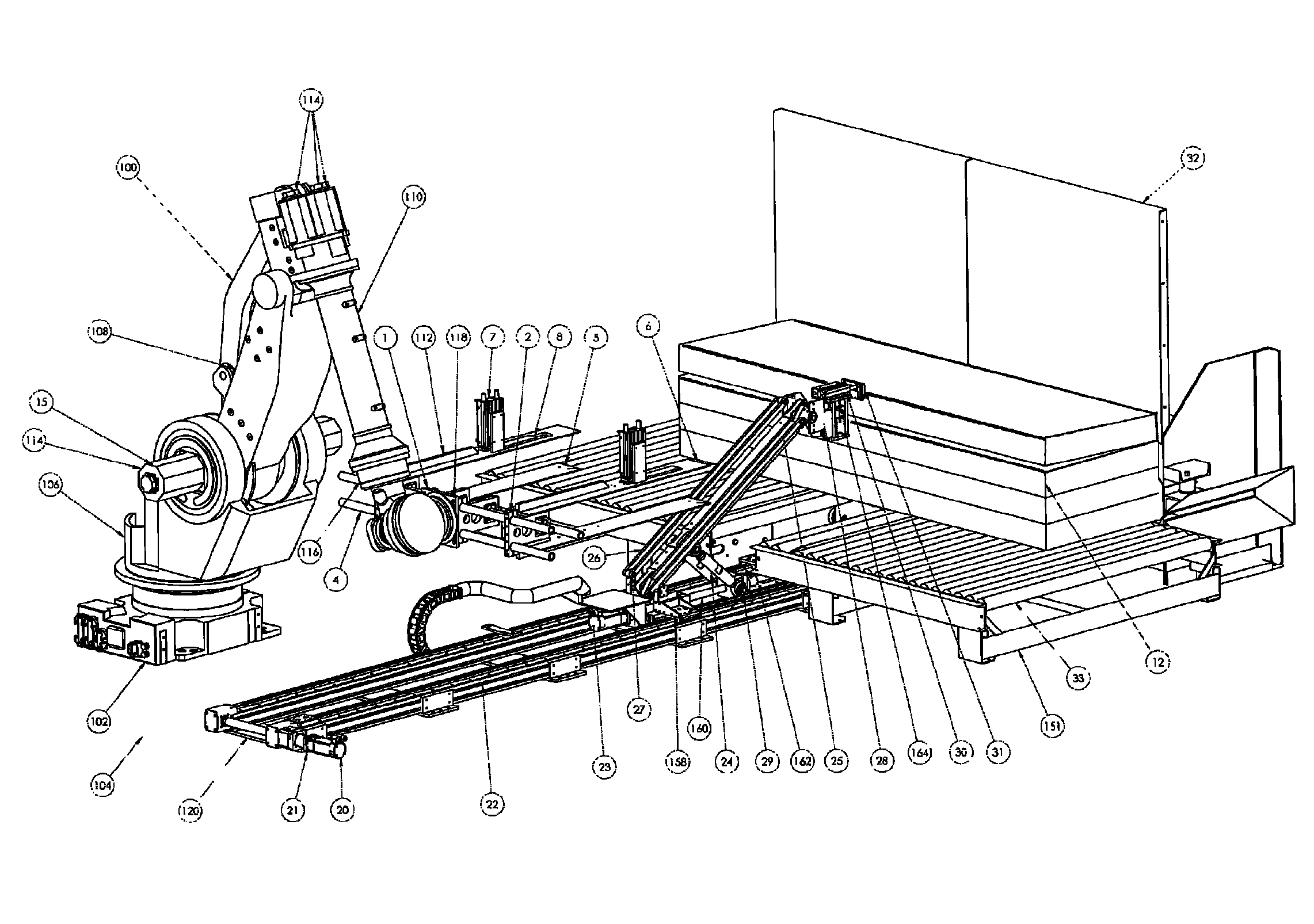
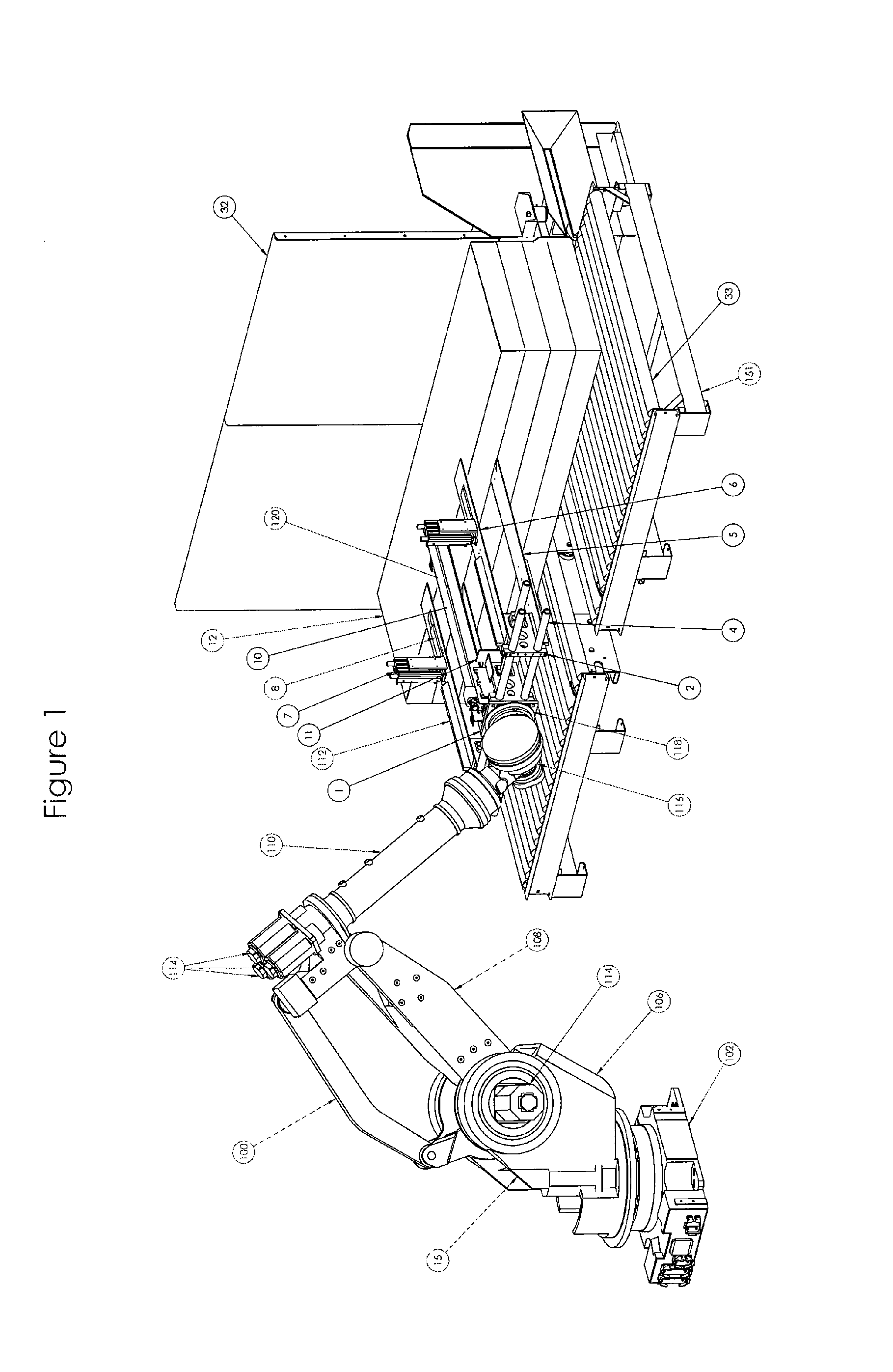
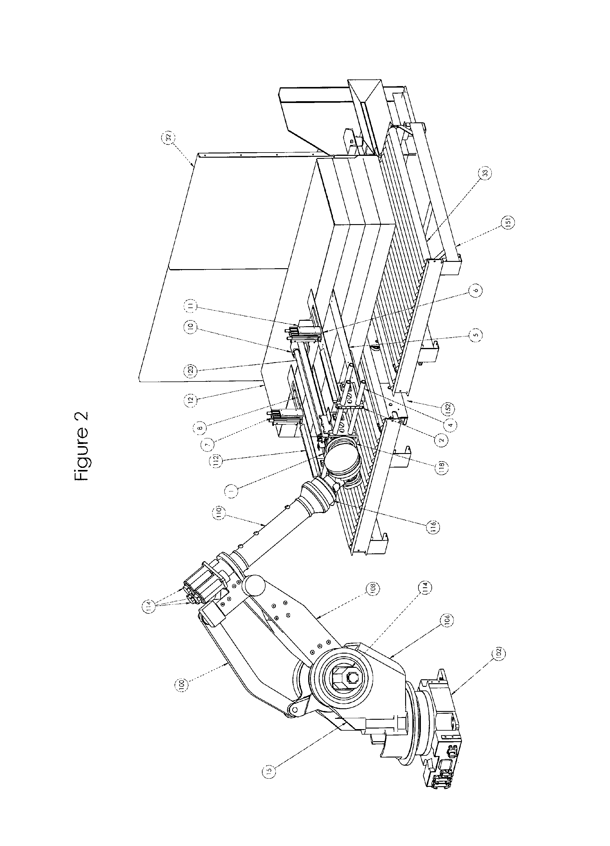
[0040]In a second embodiment for the apparatus 100′, as shown in FIGS. 6-11, 14 and 15, the separation mechanism 120′ is removed from the tooling 112′, and is instead formed as a part of the item stack support structure 151. In the illustrated embodiment, the structure 151 includes a pair of conveyors 33 disposed on opposed sides of a channel 152. The conveyors 33 are located immediately adjacent a backstop 32 which maintains the alignment of the stacks of items 12 moving along the conveyors 33. The conveyors 33 can be connected to, or may form part of a larger conveyance system (not shown) capable of successively moving stacks of items 12 into position over the channel 152, which has a width less than that of the items 12 forming the stack, such that the conveyors 33 effectively support the stack of items 12 on opposite sides of the channel 152.

[0041]Referring now to FIGS. 14 and 15, the separation mechanism 120′ is disposed in alignment with the channel 152 and includes a pair of ...

first embodiment

[0047]Subsequently the cylinder 29 is operated to elevate the housing 160 and separator plate 31, thereby forming a separation or gap 150 between adjacent items 12 in the stack at the desired location in the stack, as shown in FIG. 9. With the gap 150 formed between the desired number of items 12 and the remainder of the stack of items 12, the arm 15 can be operated to move the lower forks 5 into the gap 150 and the upper forks 6 over the top of the stack of items 12, as shown in FIG. 10. When the forks 5 and 6 are properly positioned with respect to the items 12 located therebetween, the air cylinders 7 on the upper forks 6 can be operated as described with regard to the first embodiment to secure the items 12 between the pads 8 and the lower forks 5.

[0048]At this point, the motor 20 and / or 23 can simultaneously or subsequently be operated to retract the plate 31 from the stack of items 12, thereby again preventing the mechanism 120′ from interfering with the movement of the arm 15...


PUM

PropertyMeasurementUnit
thicknessesaaaaaaaaaa
operational flexibilityaaaaaaaaaa
thicknessaaaaaaaaaa

Abstract

An apparatus for separating and moving a selected number of items, such as a sheets, boards or blanks is provided in which a robotic arm is constructed with forks capable of securely compressing a desired number of items therebetween for displacement from a stack of the items. The items to be grasped by the arm are initially separated from the remainder of the stack by a separation mechanism that can be mounted directly to the arm or to a support structure for the stack of items. The separation mechanism engages and lifts the desired number of items from the stack to enable the forks on the arm to engage each side of the items. The apparatus can be quickly reconfigured to engage and remove any desired number of items from the stack and/or to accommodate changes I the shape, size and/or thickness of the items.

Description

FIELD OF THE INVENTION[0001]The present disclosure relates to lifting devices, and more particularly to an apparatus for lifting stacks of material or items and moving the items to a desired location with a desired orientation.BACKGROUND OF THE INVENTION[0002]Materials and items for use in a variety of manufacturing and other processes are often placed in stacks to enable the items to be more economically positioned and utilized within the processes. For example, many items are shipped from their location of origin to an assembly location where the materials or items are combined with other items to form a completed product. In shipping these materials / items, the items are often placed in stacked configurations on pallets or other similar structures in order to ship a number of the items at the same time in an economic manner.[0003]When placed in these stack configurations, on difficulty is removing the desired number of items from the stack for use in the process. This is a particu...

Claims


Application Information

Patent Timeline
Patent Type & Authority Patents(United States)
IPC IPC(8): B65H3/24B65G59/00B65H1/08
CPCB65G47/90B65G59/023B65G59/00B65H1/08B65H3/24B25J15/0014B65H2555/31B65H2301/42242B65H3/322B65H2701/1764B27B31/00B65H2555/30B65H83/025B65H2301/4223
Inventor WIDDER, KEVINDAVIS, DANIELCLUSSMAN, JOSEPHSCHNEIDER, DANIEL
Owner AUTOMATAN LLC
Why Eureka
Try Eureka