
Flameless candle with fragrance diffusion

a flameless candle and fragrance technology, applied in the field of flameless candles, can solve the problems of affecting the fragrance of the candle, and consuming a relatively large amount of power for the heater element, so as to achieve the effect of promoting airflow

Inactive Publication Date: 2014-07-22
STERNO HOME INC
View PDF74 Cites 34 Cited by
  • Summary
  • Abstract
  • Description
  • Claims
  • Application Information

AI Technical Summary

Benefits of technology

The patent describes a flameless candle that includes a housing with a hollow region and a recessed area above it. The recessed area retains a fragrant substance and air, and there is a vent hole that allows air to flow from the hollow region and into the recessed area. This airflow can draw the fragrant substance from the air above it, creating a fragrant atmosphere. The flamless candle also has a cover that can cover the reservoir and a handle that resembles a wick. The cover has perforations that allow airflow and legs that control airflow. The base of the flamless candle can be elevated above a resting surface and has holes that allow airflow. The patent also describes how the flamless candle can create a fragrant atmosphere without the need for a flame.

Problems solved by technology

However, such heating can accelerate thermal decay of fragrant materials or change their character.
Additionally, such heater elements may consume a relatively large amount of power, especially if the candle is portable.
Other flameless candles may employ air freshener wicks which may cause fractional distillation evaporation from the moistened wick surface.
Such an effect may change the character of the fragrance over time.
However, it may be difficult or expensive to vary the amount of airflow generated by the fan.
Furthermore, the fan may blow air directly into or onto a fragrant material.
This may result in a fragrance that is relatively intense and may cause the fragrant material to lose its fragrance more quickly.

Method used


Image

  • Flameless candle with fragrance diffusion
  • Flameless candle with fragrance diffusion
  • Flameless candle with fragrance diffusion

Examples


Embodiment Construction

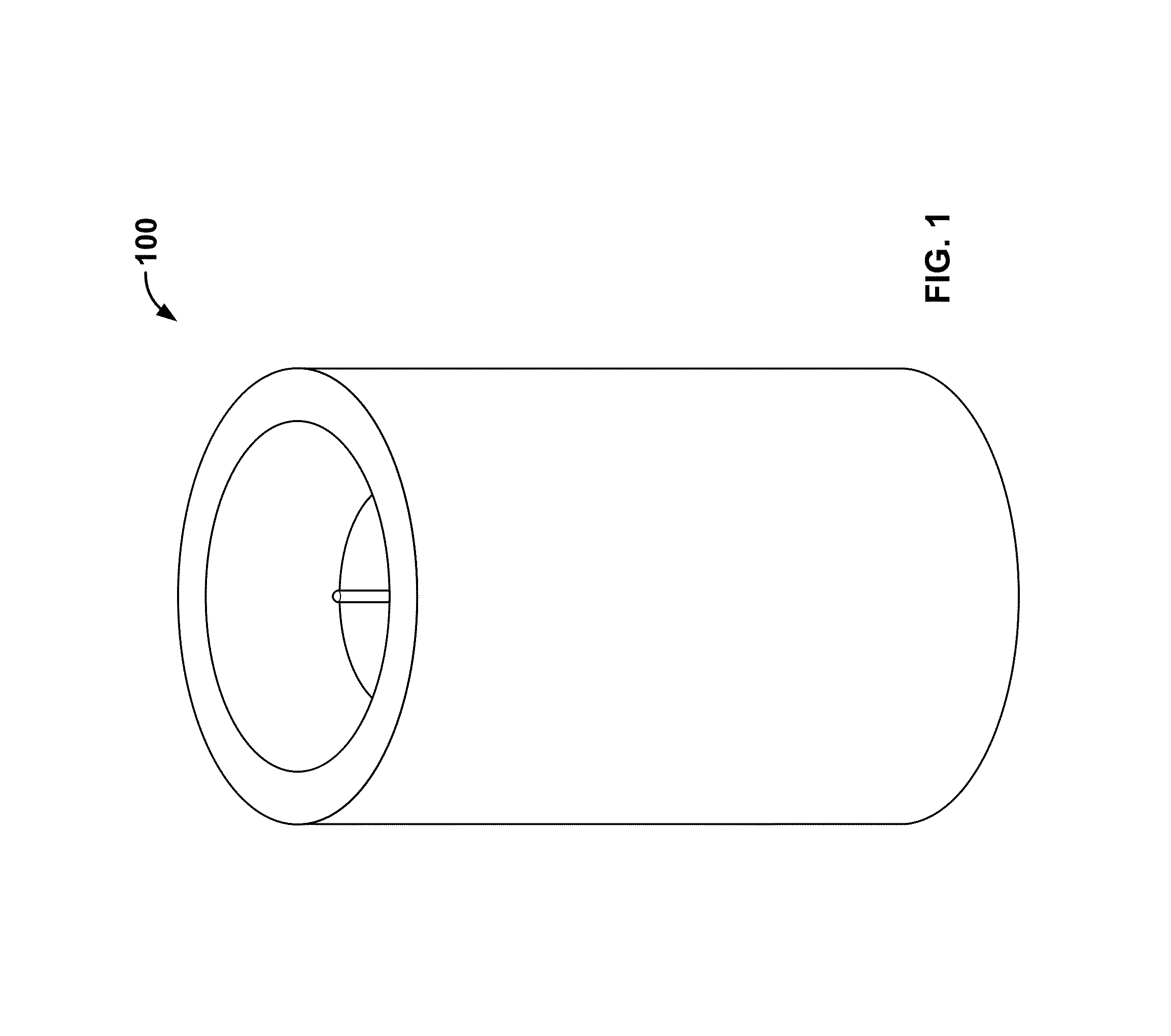
[0027]FIG. 1 shows a perspective view of a flameless candle 100, according to an embodiment of the present invention. The flameless candle 100 may appear as a conventional candle. For example, the candle 100 may have a lamp that emits a flickering light. The flameless candle 100 may also emit a fragrance.

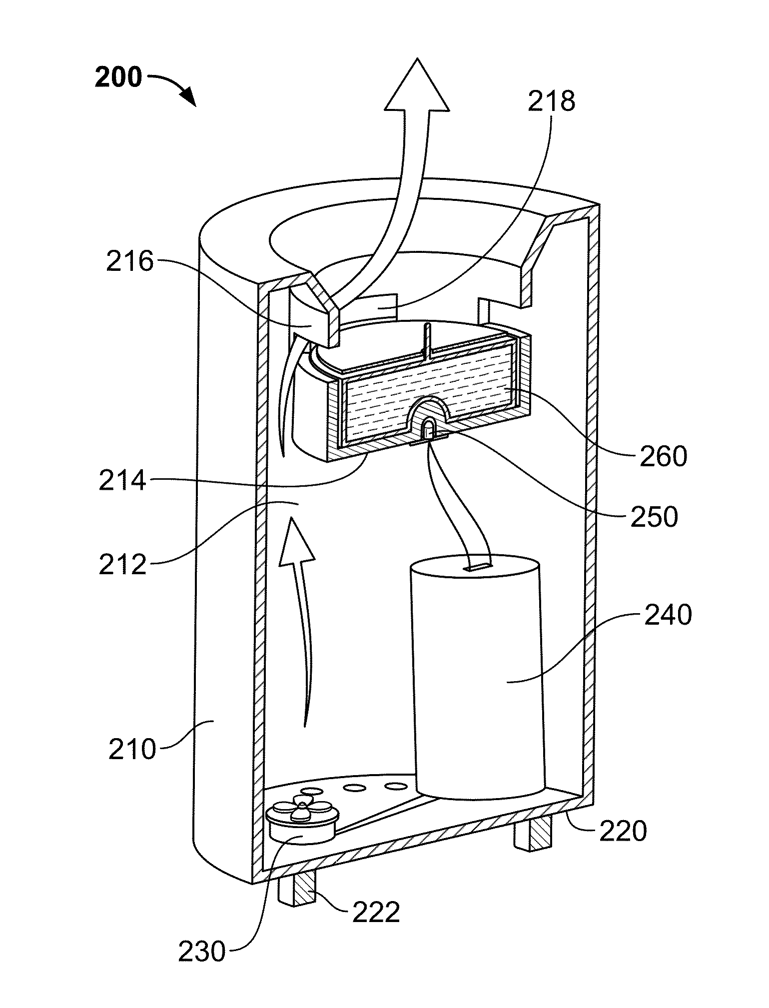
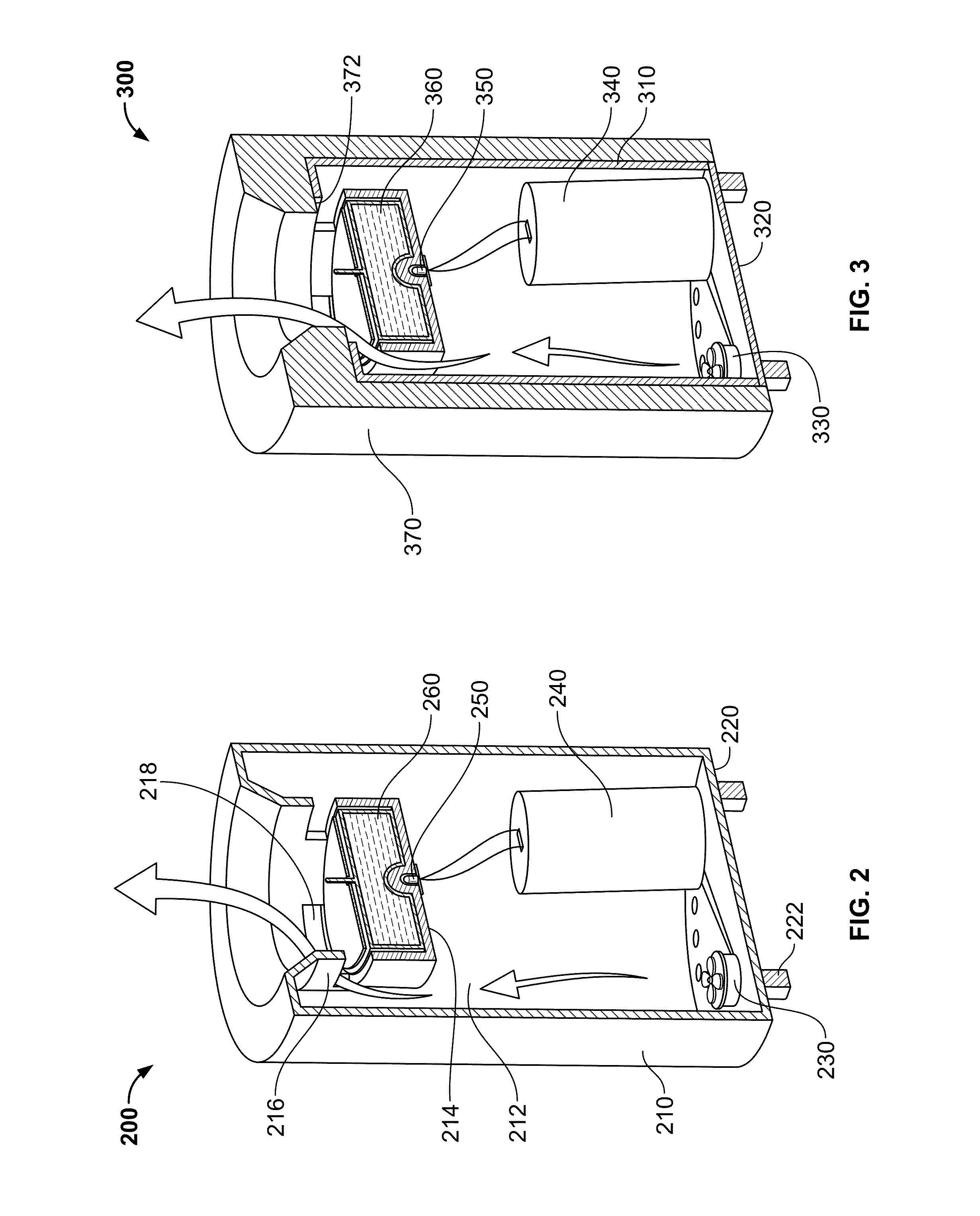
[0028]FIG. 2 shows a cross-sectional view of a flameless candle 200, according to an embodiment of the present invention. The flameless candle 200 may include a housing 210, a base 220, a fan 230, a battery / electronics compartment 240, a lamp 250, and a reservoir 260.

[0029]The housing 210 may have a hollow region 212 within the housing 210. The housing 210 may also have a recessed area within a top surface of the housing 210. A portion of the recessed area may form a well in the top of the housing 210. The well may provide the appearance of a candle that has been used. The recessed area may be bounded by a bottom surface 214 and a sidewall 216. A sidewall 216 may be vertical or at a...


PUM

PropertyMeasurementUnit
recessed areaaaaaaaaaaa
radiusaaaaaaaaaa
areaaaaaaaaaaa

Abstract

According to embodiments of the present invention, a flameless candle includes a housing, a reservoir, and a lamp. The reservoir can retain a fragrant source (e.g., solid, liquid, or mix thereof. The housing has a hollow region and a recessed area within the top surface of the housing. The recessed area is bounded by a bottom surface and a sidewall. There one or more vent holes in the sidewall. If there is a plurality of vent holes, then they may encircle the sidewall. The vent hole(s) allow an airflow from the hollow region and into the recessed area above the fragrant source. The lamp can emit a light through the bottom surface of the recessed area and through fragrant source.

Description

RELATED APPLICATIONS[0001]This application claims priority to U.S. Provisional Patent Application No. 61 / 365,649 filed on Jul. 19, 2010, which is herein incorporated by reference in its entirety.FEDERALLY SPONSORED RESEARCH OR DEVELOPMENT[0002][Not Applicable]MICROFICHE / COPYRIGHT REFERENCE[0003][Not Applicable]BACKGROUND OF THE INVENTION[0004]Generally, the present application relates to flameless candles. Particularly, the present application relates to techniques for diffusing fragrance into the living space atmosphere from a flameless candle.[0005]Flameless candles may emulate conventional candles in their appearance and behavior without having the risk associated with a flame. Certain flameless candles also attempt to emulate conventional fragrance-emitting candles. One technique used by such flameless candles is to use a heater element to diffuse a fragrant substance. However, such heating can accelerate thermal decay of fragrant materials or change their character. Additionall...

Claims


Application Information

Patent Timeline
Patent Type & Authority Patents(United States)
IPC IPC(8): F21S10/04F21Y101/02F21S6/00A61L9/12F21W121/00F21S9/02F21V33/00
CPCF21V33/0028F21S6/001A61L9/122F21S9/02F21S10/04F21W2121/00F21Y2101/02F21V17/00F21Y2115/10A61L9/12A61L9/127A61L2209/12F21V23/04
Inventor MCCAVIT, KIM IRWINRAY, ROBERT HUTTONFOURNIER, BERNARDJENSEN, BRADFORD BRIAN
Owner STERNO HOME INC
Learn More