Method and apparatus for treatment of pleural effusion

a pleural effusion and pleural fluid technology, applied in the direction of suction pumps, other medical devices, suction devices, etc., can solve the problems of deterioration, increased fluid accumulation, and increased pain in patients, and achieve the effect of convenient use by trained and untrained users

Active Publication Date: 2014-07-22
PFM MEDICAL
View PDF10 Cites 1 Cited by
  • Summary
  • Abstract
  • Description
  • Claims
  • Application Information

AI Technical Summary

Benefits of technology

[0018]By employing negative air pressure to activate fluid flow through the axial cavity, and prevent backflow, air and fluid always moves in a direction away from the chest cavity, and out of the chest tube, whenever the check valve is opened by the applied negative pressure. This action by the check valve prevents both air and pathogens from entering the axial cavity where they can reach the chest, since the only time the axial cavity communicates with the exterior of the patient is on the occurrence of negative pressure pushing air and fluid out of the axial cavity of the chest tube and away from the patient. Cessation of negative pressure to the check valve at the proximal end of the chest tube, causes an immediate closure of the check valve thereby blocking pathogen entrance before it can happen.
[0021]To further protect the patient during long term use, the threadably engaged luer lock employs a U-shaped guide to align it with the central cavity of the docking component. This is most important in that it provides the convenience of a means of alignment of the luer lock with its docking component, while also providing an open slot to allow cleaning of the inside of the U-shaped guide to prevent any contaminants or pathogens from communicating with the central cavity. The central cavity of the docking component may be capped when not in use and is also easily cleaned.
[0022]The result is a device and method much safer for the patient through the provision of a one-way flow of fluid out of the pleural cavity and cessation of flow, once the negative pressure is removed, thereby preventing pathogen migration into the chest through the very chest tube being used to aid the patient.
[0026]It is an object of this invention to provide a drainage device for pleural effusions which is easily employed by trained and untrained users.
[0027]It is another object of this invention to provide such a system which, by design, provides means to sterilize conduits and thereby prevents migration of pathogens outside the patient's body into the chest tube and chest where it can cause infection.

Problems solved by technology

However, when an individual either produces too much fluid or some other internal problem prevents normal body removal, the result is an excess of pleural fluid which forms the pleural effusion.
The accumulation of fluid, especially in patients who are already ill, is physically very uncomfortable.
It can make it hard, if not painful, for the patient to breathe along with secondary infections which can exacerbate an ill patient's condition causing further deterioration.
However, using a duckbill, or other tube-insertion activated valve has recently been found to be a source of danger in treating the patient.
Because the valve is activated by the exterior of a catheter or tube inserted between two internally housed biased blades, the blades are subject to contamination from bacteria and contaminants on the exterior of the inserted tube or from the interior of the tube once so inserted.
The design is thus inherently flawed in that it cannot be cleaned and is subject to constant contamination by tube insertion into the valve to activate it.
There are other systems for draining the pleural area inside the chest cavity but those with a chest tube which must have a sealing valve on the distal end are all subject to contamination.

Method used


Image

  • Method and apparatus for treatment of pleural effusion
  • Method and apparatus for treatment of pleural effusion
  • Method and apparatus for treatment of pleural effusion

Examples


Embodiment Construction

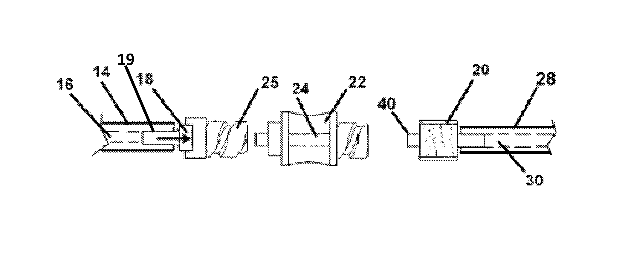
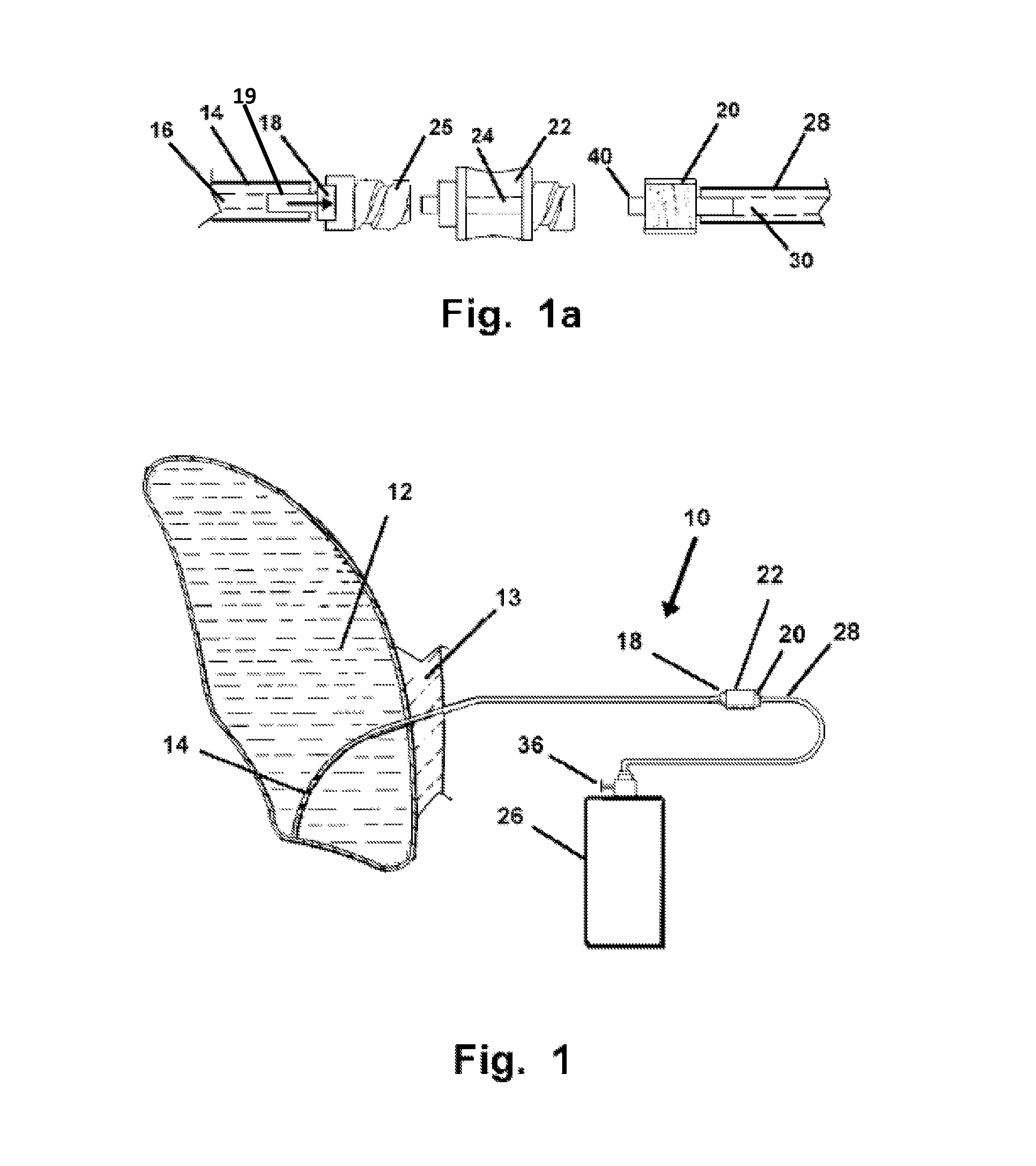
[0034]Referring now to the FIGS. 1-4, the device 10 and method herein drains fluid from pleural effusions 12 and other points of ongoing fluid accumulation in the body of a patient.

[0035]In use, the device 10 is engaged with an operatively placed chest tube 14 having a first end configured for sealed communication with a catheter 28 having a communicated negative pressure therein, and thereby cause a draining of fluid from the pleural effusion 12. The chest tube 14 is configured to communicate operatively through the patient's chest wall 13. Fluid entering the distal end of the chest tube 14 is communicated into an axial cavity 16 in a sealed communication at the proximal end of the chest tube 14 with negative pressure emanating from a catheter 28 also in sealed communication with the axial cavity 16 by way of the check valve 18.

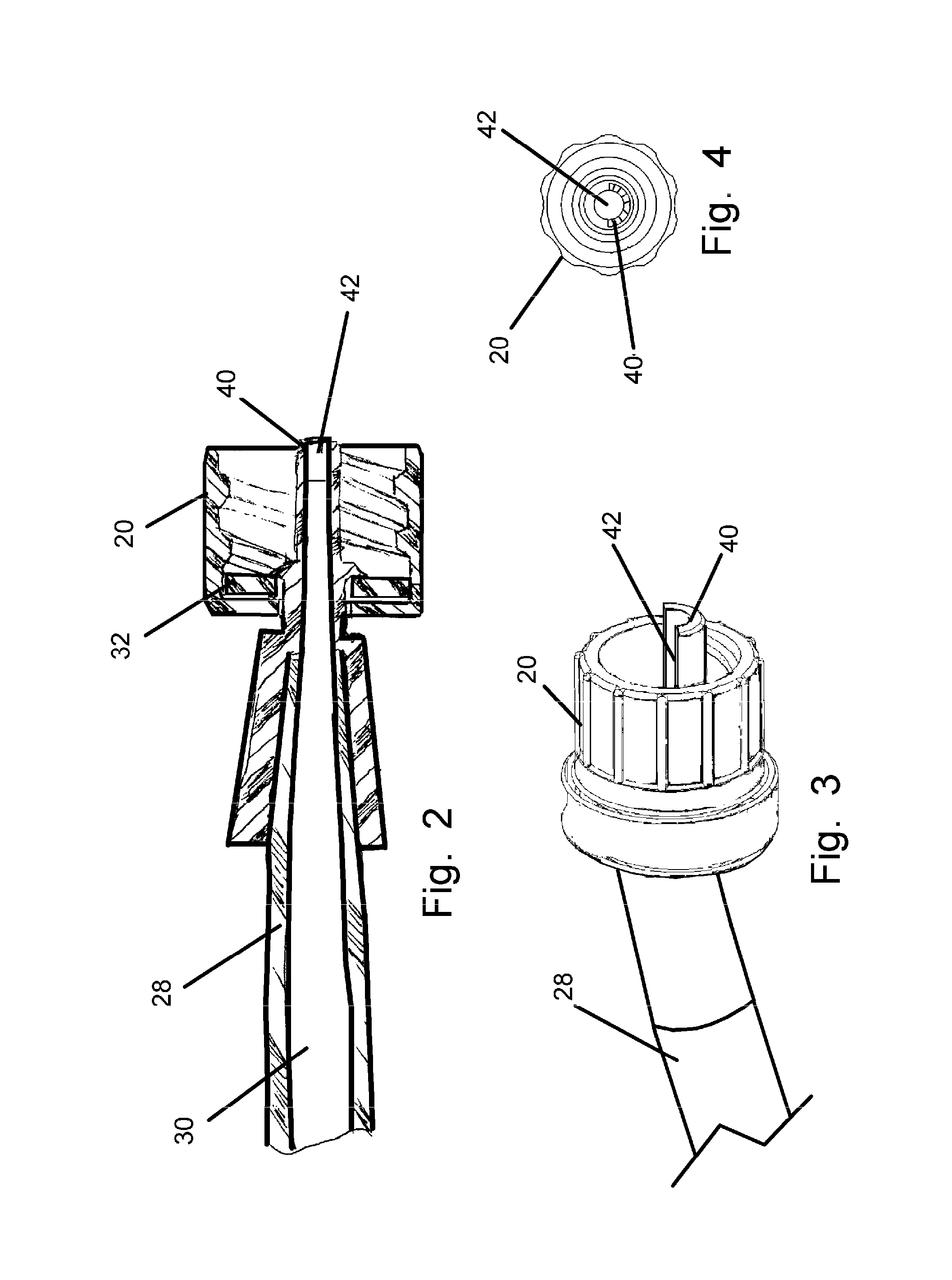
[0036]The pressure activated check valve 18 is in a sealed engagement in the pathway formed by the sealed communication between the axial conduit 30 of the ...


PUM


Abstract

A device for the drainage of a pleural effusion through an operatively engaged chest tube in the chest wall. The device employs a check valve situated between a vacuum source communicating with the chest tube to prevent reversal of the fluid flow out of the patient's body and possible contamination. A valve mounted on a vacuum bottle provides user control of communication of negative pressure from the vacuum bottle to the chest tube. Opening the valve on the bottle communicates negative pressure to the chest tube relative to the pressure in the tube thereby initiating a fluid flow out of the tube and the patient. Once the valve on the bottle is closed, fluid flow ceases and the check valve prevents reversal of the flow.

Description

[0001]This application claims priority to U.S. Provisional Application No. 61 / 227,559 filed on Jul. 22, 2009, which is incorporated herein in its entirety by reference.BACKGROUND OF THE INVENTION[0002]1. Field of the Invention[0003]The invention herein disclosed relates to medical devices for drainage of fluids from a patient during treatment. More particularly it relates to a system for drainage of fluid which unnaturally collects in the pleural space adjacent to the lung of a patient.[0004]2. Prior Art[0005]Pleural effusion is a medical condition which occurs when too much fluid collects in the pleural space of a patient. The pleural space is located in the chest cavity between the two layers of the pleura. It is more commonly known as “water on the lungs.” Symptoms of such include: shortness of breath, chest pain, gastric discomfort, and coughing.[0006]In humans, there are two thin membranes located in the chest cavity. One such membrane is the visceral pleura which is a lining o...

Claims


Application Information

Patent Timeline
Patent Type & Authority Patents(United States)
IPC IPC(8): A61M1/00
CPCA61M2039/242A61M2210/101A61M2039/1094A61M39/24A61M2039/2406A61M1/0023A61M1/0049A61M2202/0492A61M1/782A61M1/80A61M1/78
Inventor KERR, MARSHALLVAILLANCOURT, MICHAEL
Owner PFM MEDICAL
Why Eureka
Try Eureka