Covered micro gel fiber

a gel fiber and micro-gel technology, applied in the field of micro gel fibers, can solve the problems of weak mechanical strength and inability to produce woven fabrics having a microstructure, and achieve the effect of superior mechanical strength

Active Publication Date: 2014-07-22
THE UNIV OF TOKYO
View PDF8 Cites 10 Cited by
  • Summary
  • Abstract
  • Description
  • Claims
  • Application Information

AI Technical Summary

Benefits of technology

[0018]The microfiber of the present invention has superior mechanical strength, and can be suitably used for constructing a three-dimensional structure, such as a fabric structure, a cylinder structure, or a tube structure. For example, by constructing a woven fabric structure or a tube structure using the microfiber containing cells in the hydrogel, a cell structure such as a cell sheet or a cell block can be easily prepared.

Problems solved by technology

However, microfibers prepared from other hydrogel materials (for example, microfibers comprising peptide hydrogel) have a problem that they are weak in mechanical strength, and cannot be used for producing woven fabrics having a microstructure.

Method used


Image

  • Covered micro gel fiber
  • Covered micro gel fiber
  • Covered micro gel fiber

Examples


example 1 (

Reference Example)

[0075]An alginate hydrogel fiber was prepared by using a coaxial laminar flow device (Lab. Chip, 4, pp. 576, 2004; Langmuir, 23, pp. 9104, 2007) according to the method shown in FIG. 6, (A). The alginate hydrogel fiber was prepared by using 1.5% w / v sodium arginate (flow rate, Qinner=9 μl / min) as the inner fluid and a 780 mM calcium chloride solution (Qsheath=0.2 to 1.0 ml / min) as the outer fluid (FIG. 6). Gelation occurred at the merge point of the two kinds of fluids, and the diameter of the resulting fiber was 30 to 95 μm depending on the flow rate of the outer fluid (FIGS. 7, (A) and (B)). The gelled alginate hydrogel fiber was received with a petri dish containing deionized water (FIG. 7, (C)).

[0076]A copper wire (diameter: 50 μm) was passed through a glass capillary (internal diameter: 1 mm) so that the tip part formed a loop, and the alginate hydrogel fiber was caught with the loop, and drawn into the glass tube. FIG. 8, (A) is a schematic view of the drawin...

example 2 (

Reference Example)

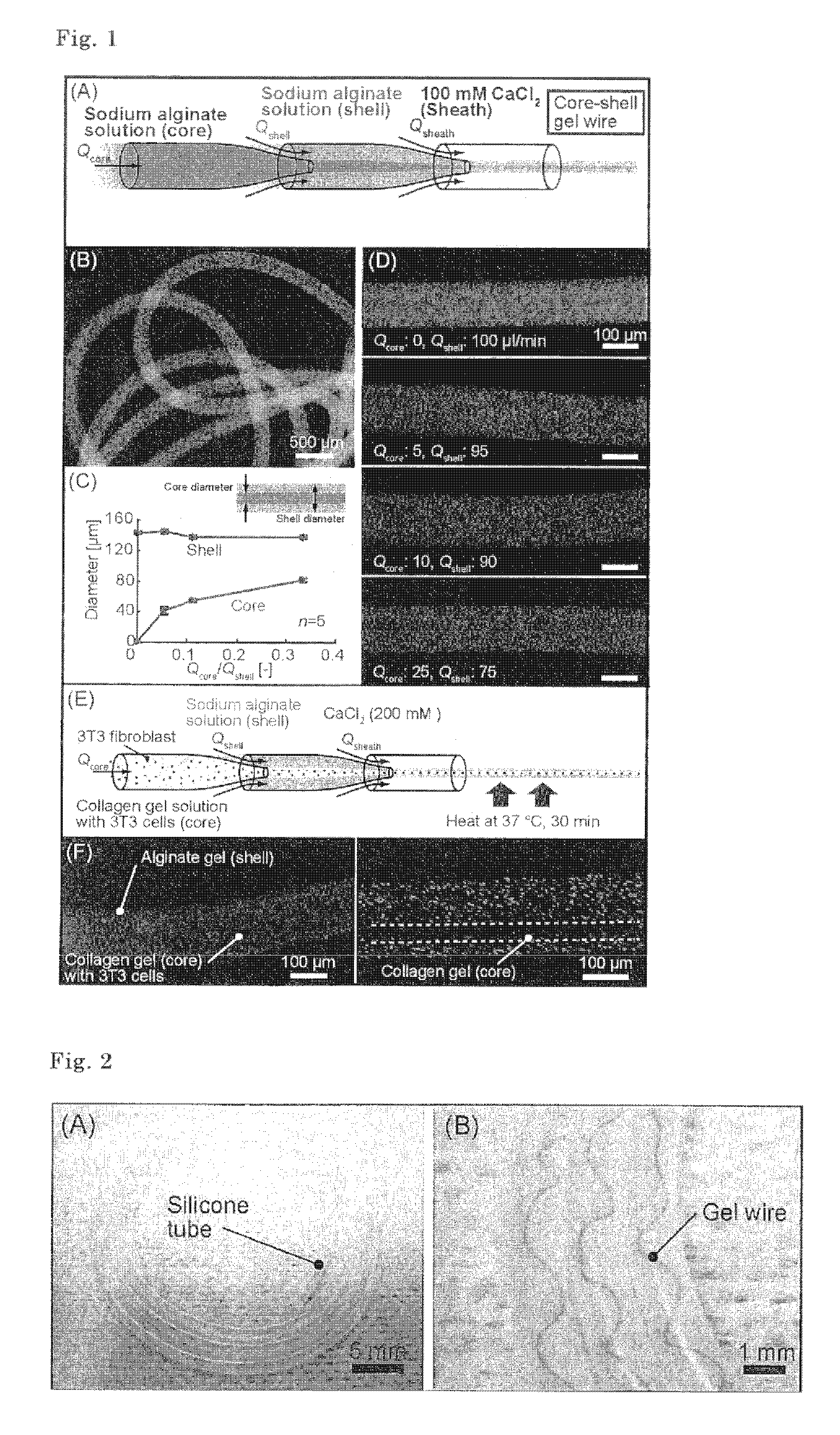
[0078]A fiber having a core-shell structure was prepared in the same manner as that of Example 1, except that a double coaxial laminar flow device (Lab. Chip, 4, pp. 576, 2004, FIG. 1) was used. As the fluid for core, 1.5% w / v sodium arginate (colored in orange) was used, as the fluid for shell, 1.5% w / v sodium arginate (colored in green) was used, and as the fluid for sheath, a 780 mM calcium chloride solution (Qsheath=3.6 ml / min) was used (FIG. 1, (A)). The resulting fiber having a core-shell structure is shown in FIG. 1, (B). The core diameter and cover thickness of the shell of the resulting fiber were varied depending on the flow rate ratio of the core fluid and the shell fluid (Qcore / Qshell) (FIGS. 1, (C) and (D)).

example 3

[0079]A microfiber consisting of a collagen micro gel fiber covered with alginate gel as the high strength hydrogel was prepared in the same manner as that of Example 2 by using a collagen solution (concentration: 2 mg / ml) containing the 3T3 fibroblasts (cell number: 1 to 10×106 cells / ml) as the fluid for core. A conceptual sketch of the method is shown in FIG. 1, (E). The resulting microfiber was a fiber having a core-shell structure in which the collagen gel as the core contained the 3T3 cells and having sufficient mechanical strength (FIG. 1, (F)).


PUM

PropertyMeasurementUnit
diameteraaaaaaaaaa
diameteraaaaaaaaaa
diameteraaaaaaaaaa

Abstract

A microfiber showing improved mechanical strength, which comprises a micro gel fiber consisting of collagen gel or the like covered with high strength hydrogel such as alginate gel.

Description

TECHNICAL FIELD[0001]The present invention relates to a micro gel fiber covered with alginate gel or the like.BACKGROUND ART[0002]Microbeads utilizing hydrogel (Advanced Materials, 19, pp. 2696, 2007; Lab on a Chip, 8, pp. 259, 2008) and microfibers utilizing the same (Lab on a Chip, 4, pp. 576, 2004; Langmuir, 23, pp. 9104, 2007; Lab on a Chip, 8, pp. 1255, 2008) have been focused because of their applicability to researches on cells and proteins. In particular, microfibers utilizing hydrogel as a base material are useful for construction of biochemical sensors (Lab on a Chip, 4, pp. 576, 2004) and artificial tissues (Langmuir, 23, pp. 9104, 2007; Lab on a Chip, 8, pp. 1255, 2008), and are expected to be useful to construct a woven fabric structure and thereby produce a complicated three-dimensional structure having a large area.[0003]Among microfibers comprising hydrogel, microfibers comprising alginate gel as a base material have sufficient mechanical strength. However, microfibe...

Claims


Application Information

Patent Timeline
Patent Type & Authority Patents(United States)
IPC IPC(8): A61K38/00
CPCD06M15/277D06M15/03D01F8/18D06M2101/14D01D5/34D06M15/576D01F8/02Y10T442/614D01D5/06D06M15/13D03D15/0061D03D15/33
Inventor TAKEUCHI, SHOJIONOE, HIROAKIMATSUNAGA, YUKIKOKIRIYA, DAISUKEGOJO, RIHONEGISHI, MIDORI
Owner THE UNIV OF TOKYO
Why Eureka
Try Eureka