Multi-path power switch scheme for functional block wakeup

a multi-path power switch and functional block technology, applied in the field of integrated circuits, can solve the problems of high total leakage current in the integrated circuit, static power consumption, and power gating, and achieve the effects of limiting the amount of overlap time, and controlling the amount of power supply nois

Active Publication Date: 2014-07-22
APPLE INC
View PDF10 Cites 10 Cited by
  • Summary
  • Abstract
  • Description
  • Claims
  • Application Information

AI Technical Summary

Benefits of technology

[0012]Powering up transistors sequentially and in groups within a functional block may control current received into the functional block during the power on procedure. This in turn may control the amount of power supply noise (which is a product of inductance and the change in current) produced during the powering on of a functional block. Similarly, powering on functional blocks sequentially and limiting the amount of time of overlap when concurrently powering on two functional block may also control the amount of power supply noise by controlling transient current within the integrated circuit.

Problems solved by technology

Leakage currents in the idle transistors lead to static power consumption.
The faster transistors (those that react to input signal changes, e.g. on the gate terminals) also tend to have the higher leakage currents which often results in high total leakage currents in the integrated circuit, especially in high performance devices.
Power gating presents challenges to the integrated circuit design.
As blocks are powered up and powered down, the change in current flow to the blocks can create noise on the power supply connections.
The noise can affect the operation of the integrated circuit, including causing erroneous operation.
When these factors slow the rate of change of the current, the delay incurred in enabling a power gated block may increase correspondingly.

Method used


Image

  • Multi-path power switch scheme for functional block wakeup
  • Multi-path power switch scheme for functional block wakeup
  • Multi-path power switch scheme for functional block wakeup

Examples


Embodiment Construction

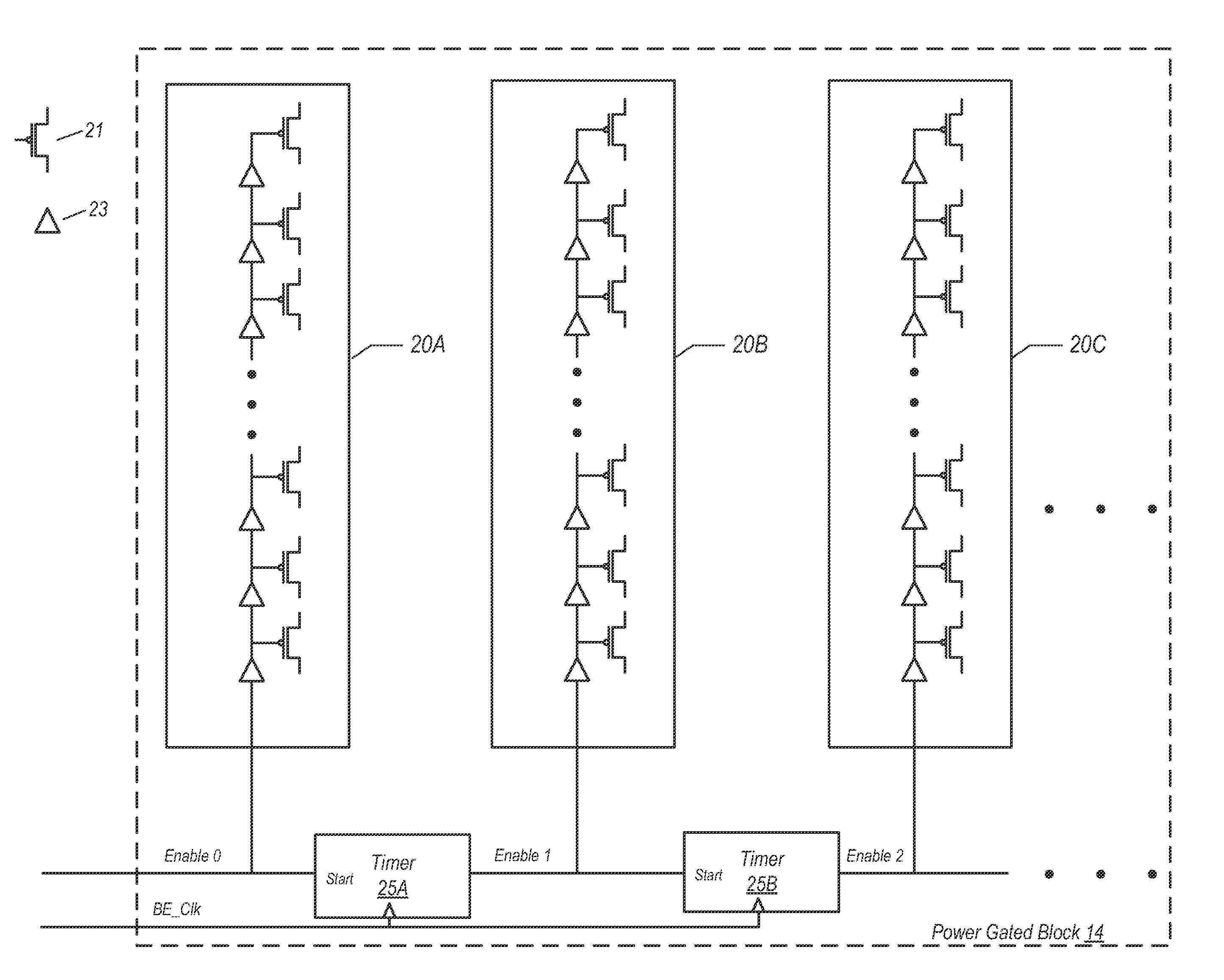
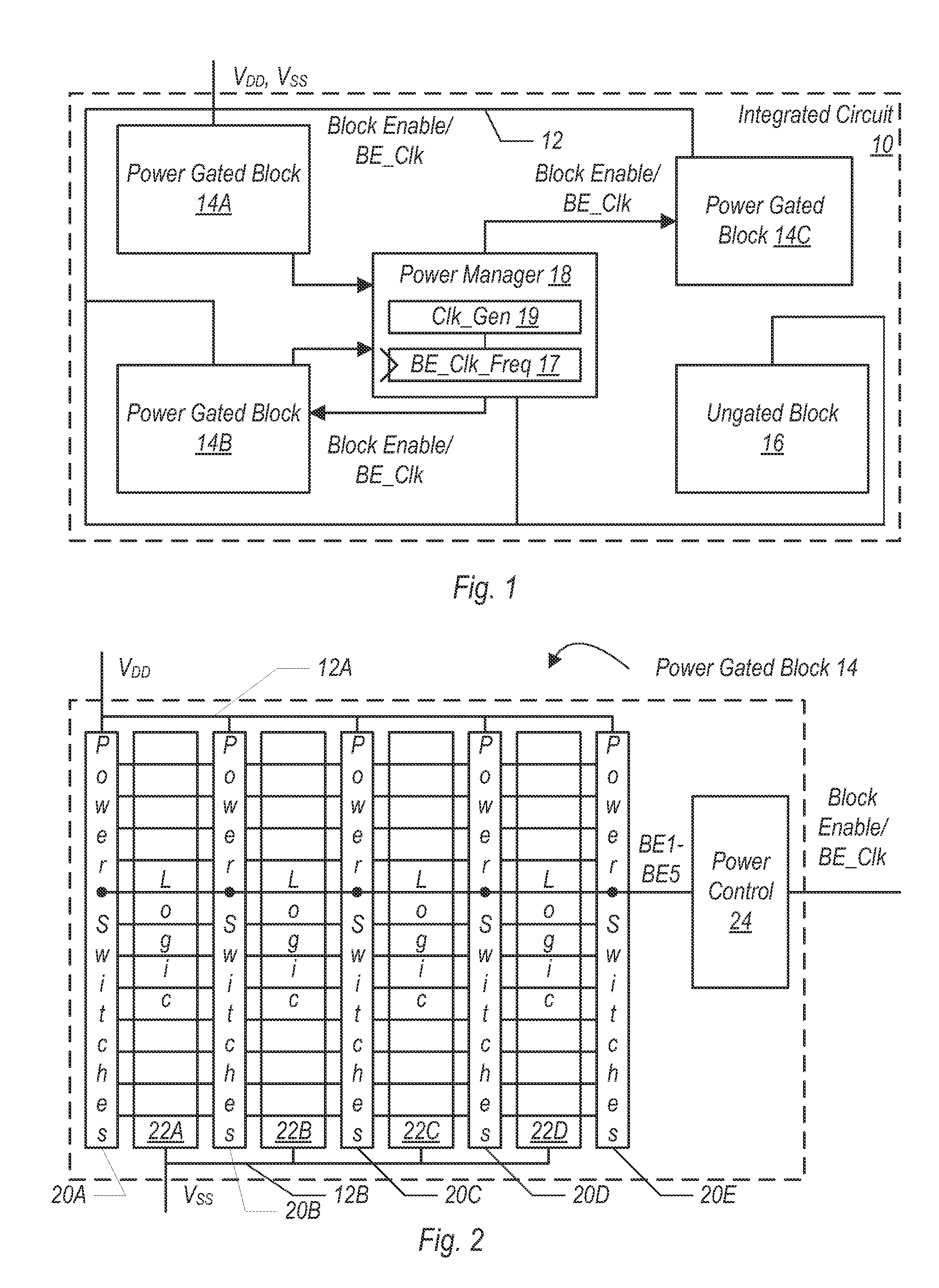
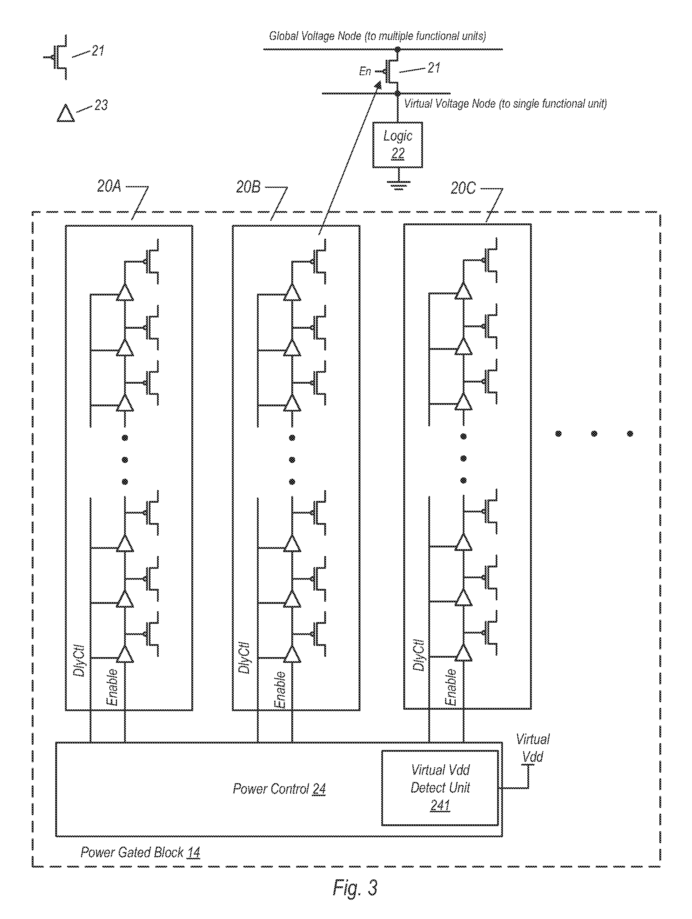
[0031]The present disclosure is directed to various method apparatus embodiments for powering up power gated functional blocks of an integrated circuit. The integrated circuit may include at least one global voltage node that may be defined as a voltage node coupled to multiple power gated functional blocks. Each functional block may include a corresponding local (or virtual) voltage node that is unique to that functional block. As defined herein, a virtual voltage node is a voltage node that is coupled to a global (e.g., supply) voltage node when one or more power switches (e.g., transistors) coupled therebetween is activated. When a power gated functional block is actively receiving power, the power switches coupled between the virtual and global voltage nodes may be activated, and the virtual voltage node may be at or near the same voltage as the global voltage node. When a power gated functional block is inactive while the supply voltage node is otherwise receiving power, the po...


PUM


Abstract

A multi-path power switch scheme for functional block wakeup is disclosed. The scheme may be applied to functional blocks of an integrated circuit. When a power on procedure is initiated within a given functional block, a first group of power switches in a functional block may be powered on, while a second group of power switches is inhibited from powering on. After a predetermined time has elapsed, activation of the second group of power switches is initiated. After initiation of a power up procedure for a given functional block, the powering up of a second functional block to be powered on may initially be inhibited. After a predetermined time has elapsed, the powering on of the second functional block may be initiated. Overlap between times when the first and second groups of switches are active may depend on process, voltage, and temperature variations.

Description

BACKGROUND[0001]1. Field of the Invention[0002]This invention relates to integrated circuits, and more particularly, to integrated circuits having power gated functional blocks.[0003]2. Description of the Related Art[0004]As the number of transistors included on an integrated circuit “chip” continues to increase, power management in the integrated circuits continues to increase in importance. Power management can be critical to integrated circuits that are included in mobile devices such as personal digital assistants (PDAs), cell phones, smart phones, laptop computers, net top computers, etc. These mobile devices often rely on battery power, and reducing power consumption in the integrated circuits can increase the life of the battery. Additionally, reducing power consumption can reduce the heat generated by the integrated circuit, which can reduce cooling requirements in the device that includes the integrated circuit (regardless of whether it is relying on battery power).[0005]Cl...

Claims


Application Information

Patent Timeline
Patent Type & Authority Patents(United States)
IPC IPC(8): H03K19/23G06F1/18G06F1/26H03K17/0412
CPCG06F1/189G06F1/26
Inventor TAKAYANAGI, TOSHINARISUZUKI, SHINGO
Owner APPLE INC
Why Eureka
Try Eureka