Rotary joint for radio frequency electromagnetic waves and light waves

a radio frequency electromagnetic and light wave technology, applied in waveguide type devices, instruments, optical elements, etc., can solve the problems of large, heavy, complicated designs, and not particularly suitable for modern, compact systems, and the device does not employ optical anti-reflection techniques to reduce the degradation of light wave signals. , to achieve the effect of minimizing optical signal degradation, reducing mechanical structure and maximum compactness

Active Publication Date: 2014-07-22
LORENC CURTIS D
View PDF5 Cites 27 Cited by
  • Summary
  • Abstract
  • Description
  • Claims
  • Application Information

AI Technical Summary

Benefits of technology

[0010]Since modern rotary antenna systems are typically designed for maximum compactness and light weight, and each antenna system typically has two rotary joints (one in azimuth and one in elevation), it is desirable to use the most efficient, compact mechanical structure possible for the rotary joint. A method of making the mechanical structure more compact is by having the connecting waveguide transmission line act as the support structure to an in-line, or axial, rotary joint. A preferred embodiment of the device of the present application provides a compact, rotationally stable, relatively simple axial rotary joint that uses the connecting waveguide as an axial support as illustrated in FIG. 14. The main connecting waveguide transmission line is the only necessary external support structure for this simpler, lighter weight device, and eliminates the need for the fixed mounting plate or fixed member of the prior art illustrated in FIG. 13. The axial approach allows for fully independent rotation of either section of the rotary joint because no section of the rotary joint is constrained by a “fixed part”.
[0011]A preferred embodiment of the present application employs a triple bearing arrangement to minimize optical signal degradation due to vibration modulation and alignment issues, offering greater mechanical stability and optical signal quality than the prior art.
[0012]The axial waveguide-to-coaxial line transition assembly used in a preferred embodiment of the present application has a path for a fully integrated second transmission line, and is capable of being pressurized and tuned for lowest reflected energy with a precision impedance matching device, maximizing power handling capability.
[0013]The various embodiments of the present app

Problems solved by technology

In the prior art, combined microwave and optic rotary joints require large, heavy mounting plates or fixed members, and also bring the waveguide connections into the rotary joint from the side, perpendicular to the axis of rotation, making for large, heavy, complicated designs that are expensive to produce and not particularly suitable for modern, compact systems.
The waveguide transmission line in this device is limited to the microwave frequency range.
The devic

Method used


Image

  • Rotary joint for radio frequency electromagnetic waves and light waves
  • Rotary joint for radio frequency electromagnetic waves and light waves
  • Rotary joint for radio frequency electromagnetic waves and light waves

Examples


first embodiment

Radio Frequency Rotary Transmission Line—Operation

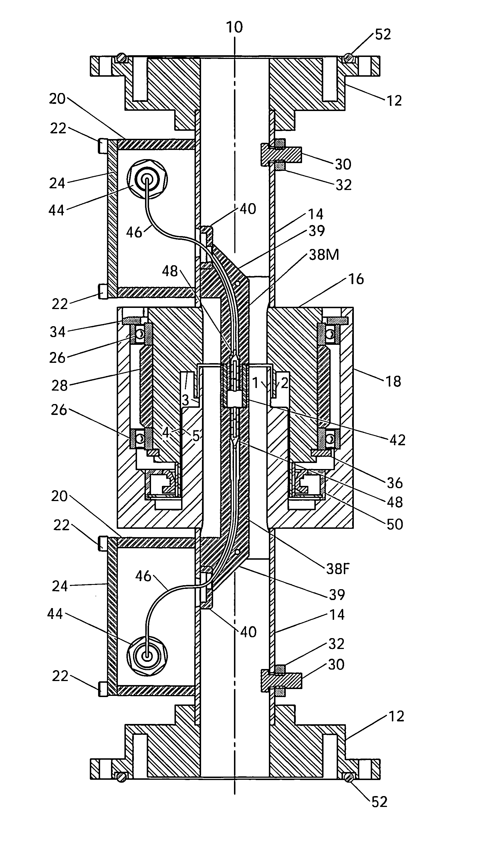
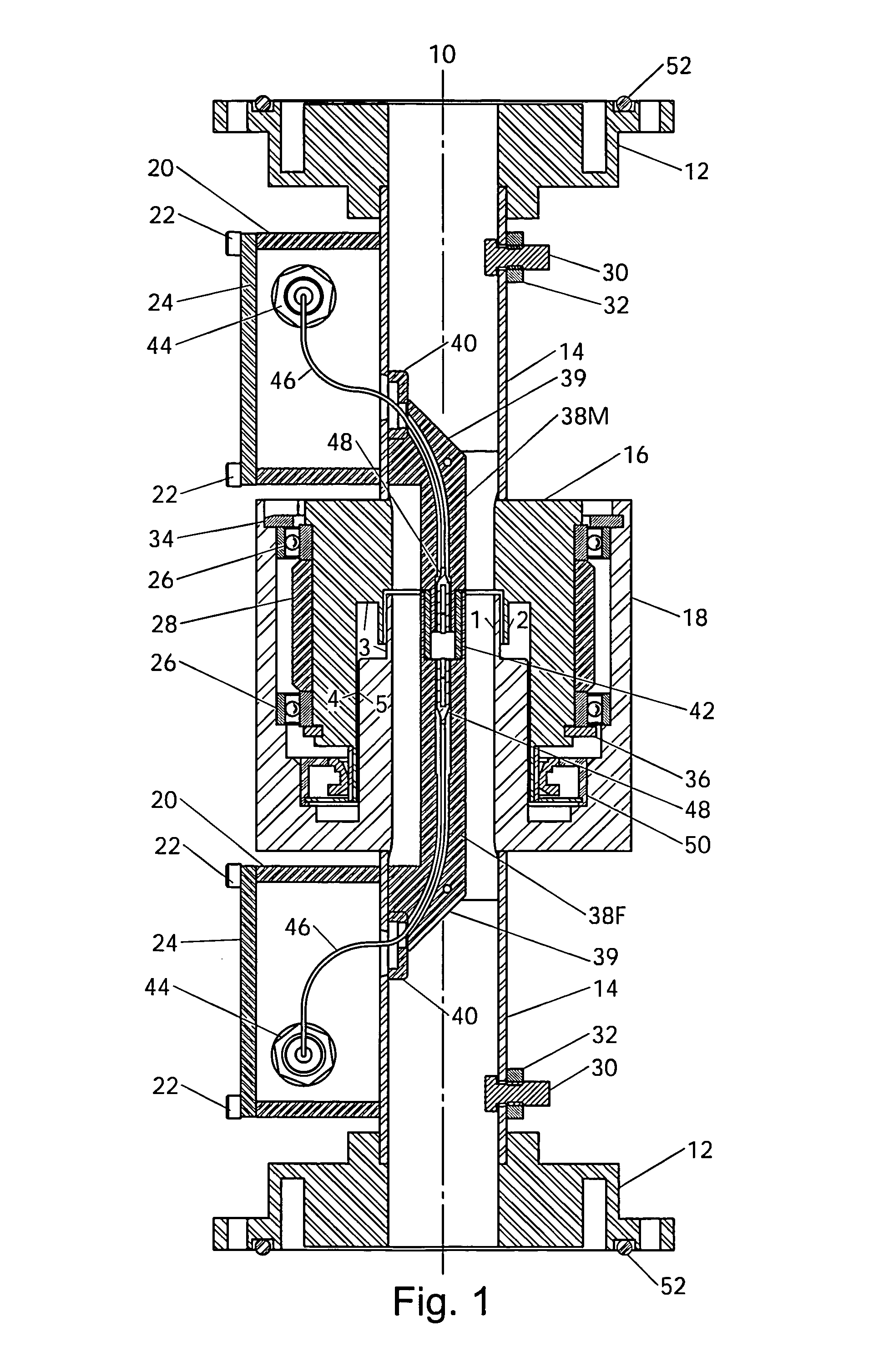
[0069]In FIG. 1, the operation of the radio frequency rotary transmission line begins with an electromagnetic wave propagating through waveguide tube 14. The waveguide-to-coaxial line transition assembly converts the electromagnetic energy from propagation through the waveguide transmission line to propagation through a coaxial transmission line that has concentric inner and outer coaxial conductors. The conversion from high-impedance waveguide to lower-impedance coaxial line is accomplished first by waveguide height-reducing plate 40 that lowers the waveguide impedance, followed by the gradual introduction of the inner coaxial conductor by inner coaxial line transition assembly 39. Inner coaxial line transition assembly 39 acts as a pick-up loop with one side attached to the waveguide outer coaxial conductor and one side attached to the inner coaxial conductor, capturing the energy from the waveguide for delivery into the coaxial tr...

second embodiment

Operation

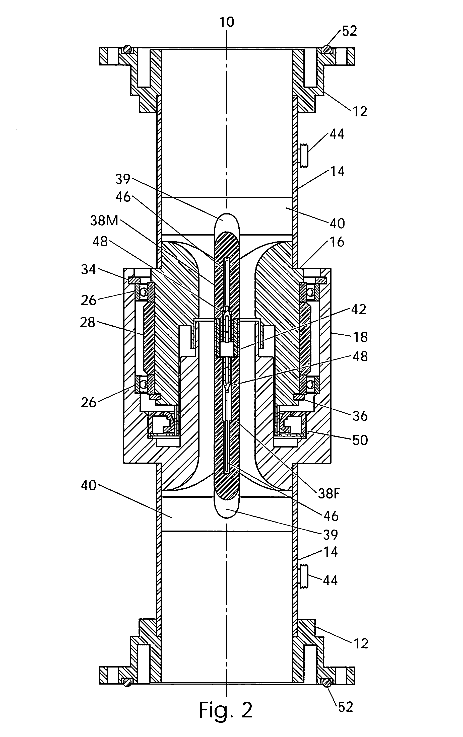
[0098]During testing of the design example of the first embodiment, an unexpected result was discovered. Very high frequency microwaves in the millimeter wave range were found to be propagating through the hollow pathway in the inner coaxial line, which was acting as a waveguide transmission line. The millimeter waves also propagated through optical coupling device 48 (FIGS. 1 & 2) and across the optical rotary interface. This discovery proved the capability of propagating different types or modes of signals through second transmission line TX2 (FIG. 3). Both light wave and millimeter wave signals were propagating through the second transmission line bi-directionally and simultaneously, resulting in a dual-mode rotary transmission line. The transmission of the millimeter wave signal was improved with the installation of millimeter waveguide tubing over the fiber optic transmission line to create a dual-mode transmission line.

[0099]Several suitable coupling devices for dual-...


PUM


Abstract

One embodiment of an axial rotary joint having rotary transmission lines for the bi-directional propagation of radio frequency electromagnetic waves and light waves across a rotary interface. Each section is capable of fully independent rotation about a common longitudinal axis. The radio frequency rotary transmission line comprises waveguide tubing at each end that transitions to a coax transmission line at the rotary interface. The waveguide tubing also functions as the axial support structure. The second transmission line for light wave propagation is fully integrated into the waveguide-to-coax transition and the inner coaxial conductor, and uses optical coupling devices to form an optical coupling path across the rotary interface. This embodiment of the rotary joint can be sealed and pressurized to minimize contamination of the optics and to increase the electromagnetic wave power handling. The second transmission line in another embodiment is a combined millimeter wave and optical transmission line supporting simultaneous millimeter wave and light wave propagation across the rotary interface. Combining and decombining filters incorporated into the physical rotary transmission lines in other embodiments create a multitude of channels on various frequencies and wavelengths, greatly increasing the usefulness of the device.

Description

CROSS-REFERENCE TO RELATED APPLICATIONS[0001]NoneFEDERALLY SPONSORED RESEARCH[0002]Not ApplicableSEQUENCE LISTING OR PROGRAM[0003]Not ApplicableBACKGROUND OF THE INVENTION[0004]1. Field[0005]This application generally relates to devices for the transfer of electromagnetic waves and light waves across a rotary interface, specifically to a bi-directional, multiple-transmission-line rotary joint with each section of the rotary joint capable of independent rotation.[0006]2. Prior Art[0007]Electronic systems that use rotatable antenna assemblies have continuously evolved to produce smaller, more compact systems with greater performance. Present trends seem to be heading toward mounting more of the system electronics on the back of the antenna to improve performance. This trend requires a greater number of high-frequency signals to be connected from the electronics on the rotatable antenna to the electronics in the system's base unit through a rotary joint.[0008]In the prior art, combined...

Claims


Application Information

Patent Timeline
IPC IPC(8): H01P1/06G02B6/36
CPCH01P1/062H01P5/103H01P1/067G02B6/3604
Inventor LORENC, CURTIS, D
Owner LORENC CURTIS D
Why Eureka
Try Eureka