Virtually oil-free shock absorber having high dissipative capacity

a shock absorber and oil-free technology, applied in vibration dampers, mechanical devices, pumps, etc., can solve the problems of poor heat exchange effect, long length of shock absorbers, and high dissipation power of such shock absorbers, so as to reduce inertia, avoid negative effects of heat exchange, and increase speed

Inactive Publication Date: 2015-01-06
WALDEN ASSOCS
View PDF5 Cites 1 Cited by
  • Summary
  • Abstract
  • Description
  • Claims
  • Application Information

AI Technical Summary

Benefits of technology

[0017]Another object of the invention is to design a shock absorber having high dissipation power and practically no oil, in which the structure makes it possible to avoid any risk or danger, during assembly, disassembly, and handling of the shock absorber, and also to achieve maximum compactness for transporting or storing the shock absorber.GENERAL DEFINITION OF THE INVENTION
[0020]each of the two working chambers also communicates via respective non-return means with an associated compensation chamber that is arranged in the corresponding end of the tubular body, said compensation chambers ensuring hydraulic fluid continuity during movements of the rod-and-piston assembly in the tubular body.
[0021]By means of the above-specified structure, the two flexible bags, each containing an associated heterogeneous structure, are close to the wall of the tubular body of the shock absorber, which is most advantageous for effective heat exchange between the porous capillary matrices and the outside. In addition, by providing two compensation chambers that are arranged at the two ends of the tubular body, it is possible to avoid any negative influence on heat exchange, and also to reduce the inertia (and thus increase the speed) with which hydraulic fluid is driven through the “working chamber and compensation chamber” system.

Problems solved by technology

Such conventional shock absorbers are very widespread, but they remain tied to a principle of energy dissipation that is obtained solely by throttling a viscous fluid, generally oil, which explains the poor dissipation power of such shock absorbers.
There also exist practical drawbacks that are inherent to their structure, in particular the fact of always being under high pressure.
The presence of such a high pressure can give rise to danger during assembly and disassembly, and also while the shock absorber is being handled.
Another drawback, which is likewise inherent to the fact of being permanently under high pressure, is that for storage or transport of the shock absorber, the rod-and-piston is in the extended position, such that the shock absorber occupies a long length.
Nevertheless, certain drawbacks have been found in the above-mentioned shock absorber structure.
Firstly, when the shock absorber uses a conventional two-chamber piston with two sealing systems, it is necessary to provide a body that extends towards the rear along a length that is sufficient to enable the rod-and-piston to penetrate completely, thereby giving rise to a shock absorber that is of considerable length, even when the rod-and-piston has penetrated completely.
Unfortunately, it is that surface which determines the effectiveness of heat exchange between the porous capillary matrices and the outside, and as a result a significant increase is observed in the temperature of said matrices in situations of severe operation and / or with high peak speeds of the rod-and-piston.

Method used


Image

  • Virtually oil-free shock absorber having high dissipative capacity
  • Virtually oil-free shock absorber having high dissipative capacity
  • Virtually oil-free shock absorber having high dissipative capacity

Examples


Embodiment Construction

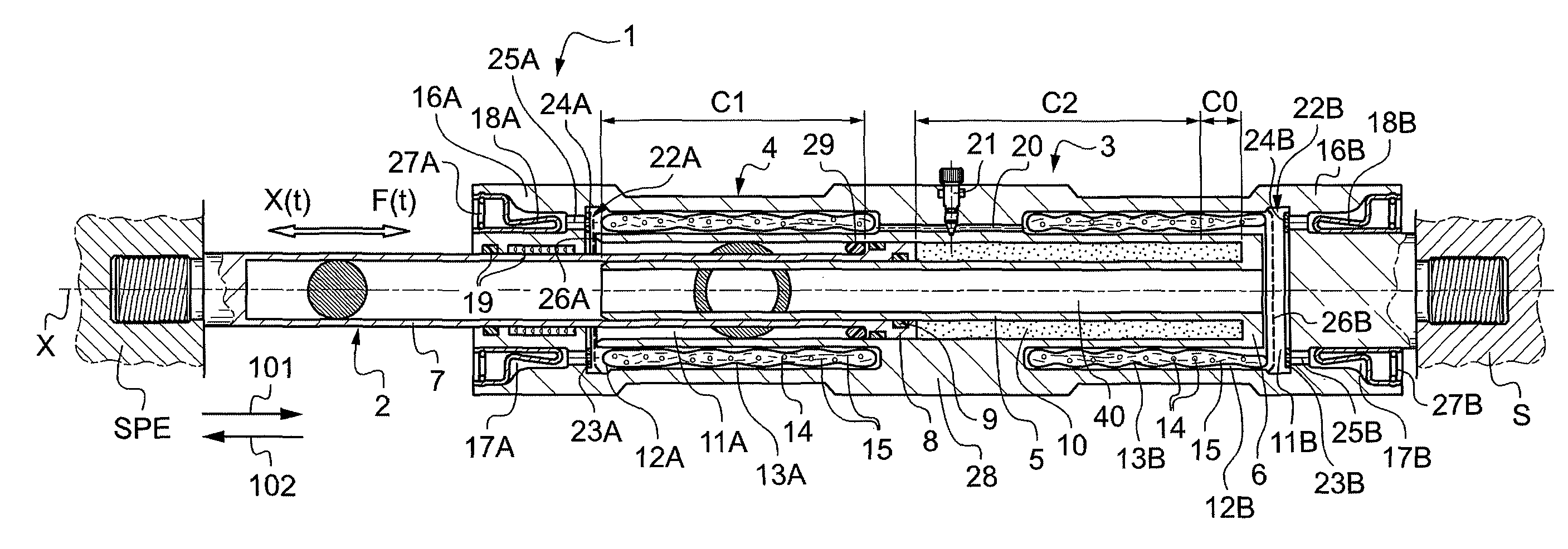
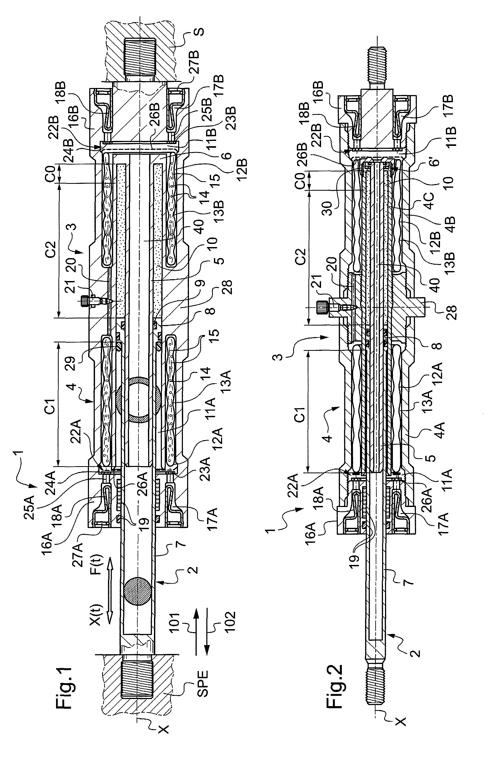
[0041]FIG. 1 shows a shock absorber referenced 1 in accordance with the invention, the shock absorber having high dissipation power and practically no oil. This shock absorber is of the type comprising a rod-and-piston assembly 2 that is slidable in a tubular body 3, said rod-and-piston assembly being adapted to be connected to an external source of disturbances referenced SPE (e.g. a wheel of a vehicle fitted with the shock absorber in its suspension, for a wheel that is in direct contact with the ground), and said tubular body is adapted to be connected to a structure that is to be protected, referenced S (e.g. the bodywork of the motor vehicle fitted therewith).

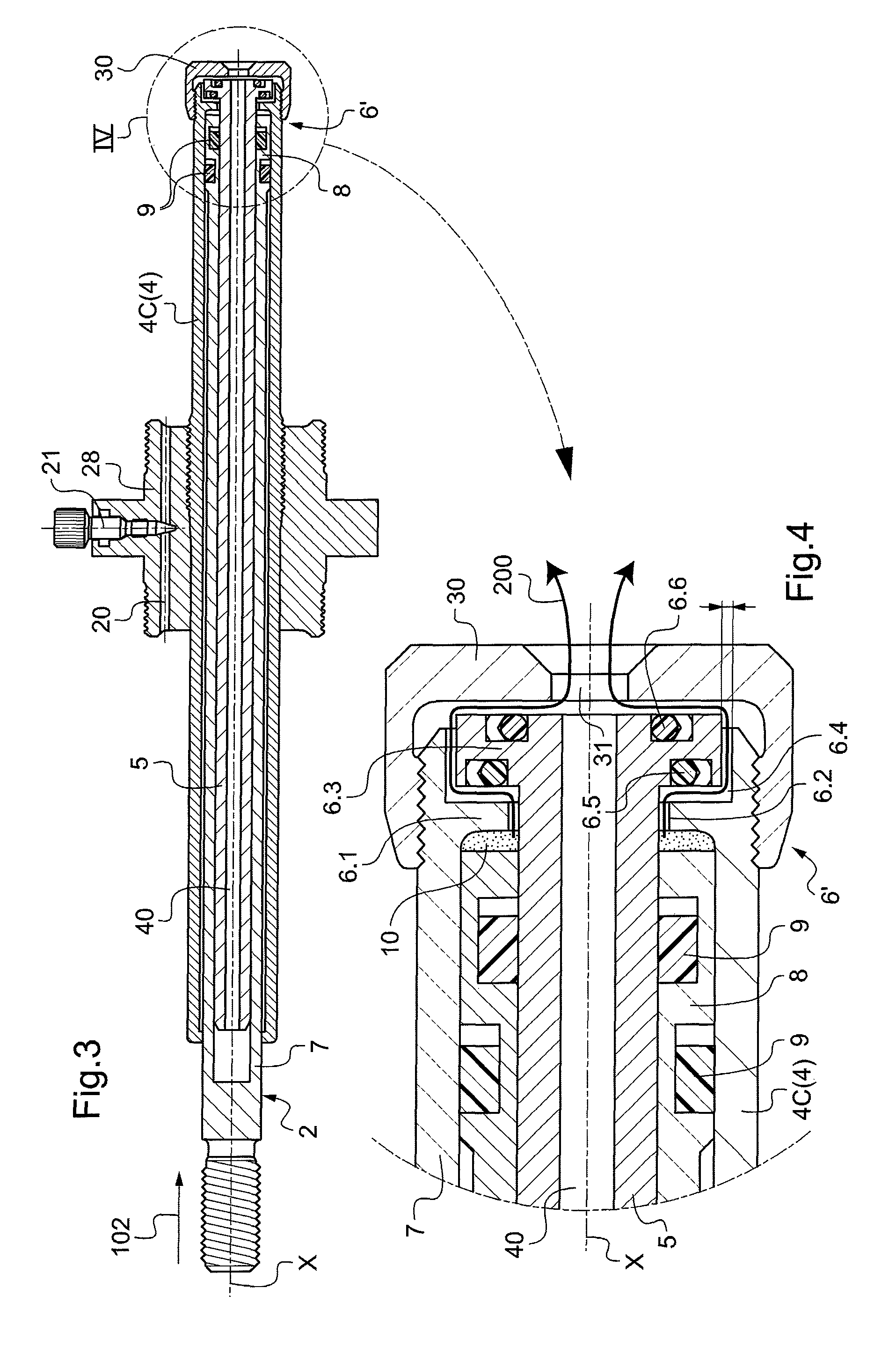
[0042]Specifically, the tubular body 3 has a cylindrical portion 4 within which an open-ended hollow central rod portion 5 extends axially, along a longitudinal axis X of the shock absorber. The ring 6 securely connecting the cylindrical portion 4 to the hollow central rod portion 5 thus forms the end wall of a chamber 10 ...


PUM


Abstract

A shock absorber has dissipation power and practically no oil. The shock absorber comprising a rod-and-piston assembly slidable in a tubular body. The rod-and-piston assembly co-operating with the tubular body to define two working chambers containing hydraulic fluid. Each working chamber being in permanent communication with an auxiliary chamber containing a heterogeneous energy absorption-dissipation structure with at least one porous capillary matrix and an associated liquid relative to which the matrix is lyophobic. The two auxiliary chambers are annular chambers formed in the wall of the tubular body on either side of central portion of the tubular body. Each of the annular auxiliary chambers houses a flexible bag containing the associated heterogeneous structure; and each of the two working chambers also communicates with an associated compensation chamber. The compensation chambers ensures hydraulic fluid continuity during movements of the rod-and-piston assembly in the tubular body.

Description

[0001]The present invention relates to a shock absorber with high dissipation power, and more particularly to a shock absorber of the type comprising a rod-and-piston assembly that is slidable in a tubular body, said rod-and-piston assembly being adapted to be connected to a source of external disturbances and said tubular body being adapted to be connected to a structure that is to be protected.BACKGROUND OF THE INVENTION[0002]In conventional hydraulic or oleo-pneumatic shock absorbers, use is made of a system comprising a rod-and-piston and a return spring, which system is interposed between the structure that is to be protected (e.g. the bodywork of a motor vehicle) and a source of external disturbances (e.g. a wheel of the vehicle in direct contact with the ground). A cylinder and rod-and-piston unit is then provided that is surrounded by the return spring and that has the function of dissipating the energy of impacts by making use of the viscous flow of a hydraulic fluid. Energ...

Claims


Application Information

Patent Timeline
Patent Type & Authority Patents(United States)
IPC IPC(8): F16F9/30F04B1/00F16F9/00F16F9/06
CPCF04B1/00F16F9/003F16F9/065F16F9/00F16F9/02F16F9/32
Inventor EROSHENKO, VALENTIN
Owner WALDEN ASSOCS
Why Eureka
Try Eureka