Extension shaft for hold a tool for rotary driven motion

a technology of extension shaft and rotary drive, which is applied in the direction of wrenches, manufacturing tools, portable drilling machines, etc., can solve the problems of difficult to use the powered instrument in limited access areas, ineffective use of hand-held instruments in spatially restricted or difficult-to-reach locations, etc., and achieve the effect of fast change of implements

Inactive Publication Date: 2014-07-29
EAZYPOWER CORP
View PDF41 Cites 8 Cited by
  • Summary
  • Abstract
  • Description
  • Claims
  • Application Information

AI Technical Summary

Benefits of technology

[0007]Accordingly, the present invention is directed to an extension shaft for holding a tool for rotary driven motion. The extension shaft is capable of being adapted to a handheld instrument having a chuck. The extension shaft includes a first end adapted to cooperate with the chuck and be releasably retained thereby; and a second end adapted to releasably retain the tool for rotary driven motion. The first end of the extension shaft and the chuck have complementarily shaped non-circular cross-sections, wherein the first end has an axis and is capable of being releasably retained by the chuck. The second end of the extension shaft includes a tool holder for holding the tool for rotary driven motion thereof. The tool holder and the tool have complementarily shaped non-circular cross-sections. The tool holder further includes a base portion and a swivel portion. The swivel portion is capable of releasably retaining the tool within the tool holder and is pivotly coupled to the base portion through a pivot assembly. The pivot assembly may include a ball joint operatively connecting the swivel and base portions of the tool holder. Alternatively, the pivot assembly may include a first and a second pin, shaft, or axle, wherein the first and second pins of the pivot assembly are substantially perpendicular to each other and lie substantially within a plane. In either embodiment of the pivot assembly, the tool is capable of being rotated about an angle with respect to an axis of the chuck or extension shaft through rotation of the extension shaft in response to rotation of the chuck. Thus, the tool holder of the present invention provides for the handheld instrument's effective operability to be maintained throughout an increase in the angular variation between the extension shaft and the tool.
[0008]In an additional embodiment of the tool holder, the pivot assembly includes a means for biasing the base and swivel portions into axial alignment when the tool holder is at rest. The predisposition of the pivot assembly to axially align the base and swivel portions will effectively steady the swivel portion and facilitate the insertion and / or removal of the tool.
[0009]In another embodiment of the present invention, a sheath may be placed over the cooperating moving parts of the tool holder to guard against contact therewith while simultaneously allowing the extension shaft to properly operate. The sheath can be a single, unitary piece or multiple pieces. In an alternate embodiment to guard against contact with the moving parts of the tool holder, a spacer can be placed proximate the pivot assembly, e.g., bearing of the ball joint; which will assist in preventing an operator from contacting the area around the rotating and hinging parts of the tool holder.

Problems solved by technology

As a result, the handheld instrument may at times be rather ineffective for use in spatially confined or difficult-to-reach locations.
For this reason, it has been difficult to use the powered instrument in areas of limited access.

Method used


Image

  • Extension shaft for hold a tool for rotary driven motion
  • Extension shaft for hold a tool for rotary driven motion
  • Extension shaft for hold a tool for rotary driven motion

Examples


Embodiment Construction

[0046]While this invention is susceptible to embodiments in many different forms, there are shown in the drawings and will herein be described in detail, preferred embodiments of the invention with the understanding that the present disclosures are to be considered as exemplifications of the principles of the invention and are not intended to limit the broad aspects of the invention to the embodiments illustrated.

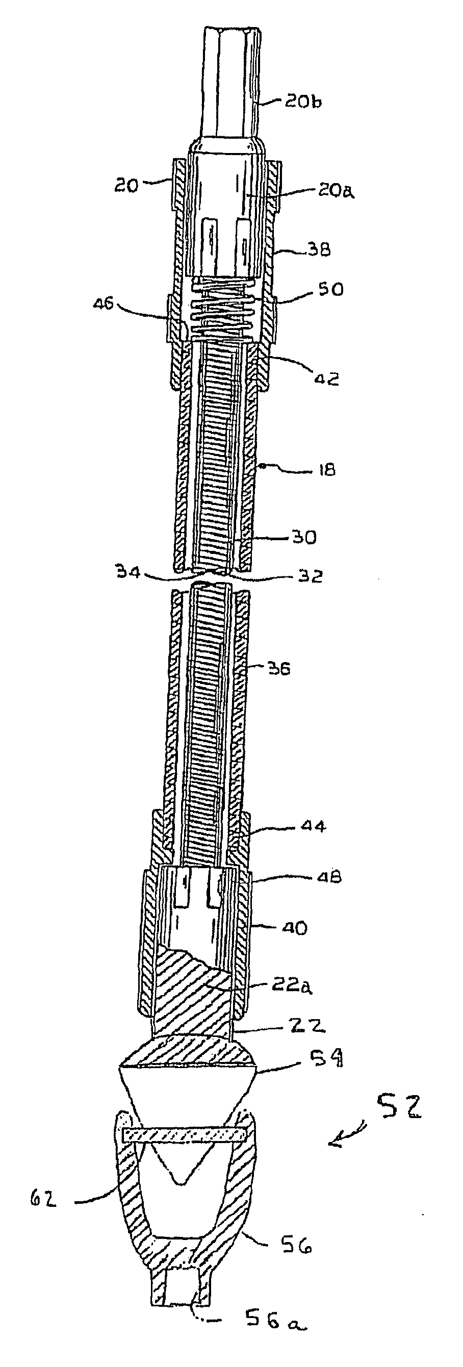
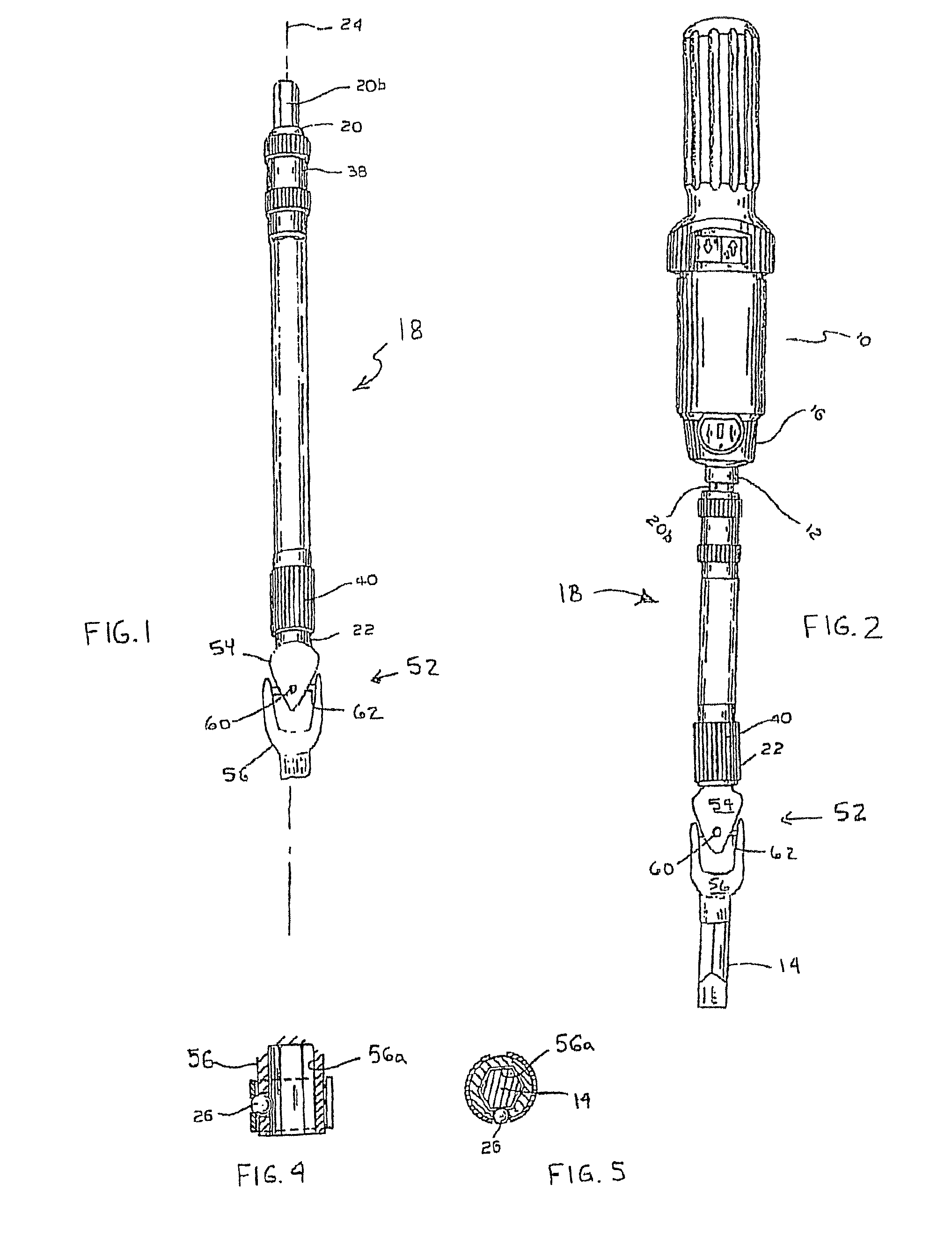
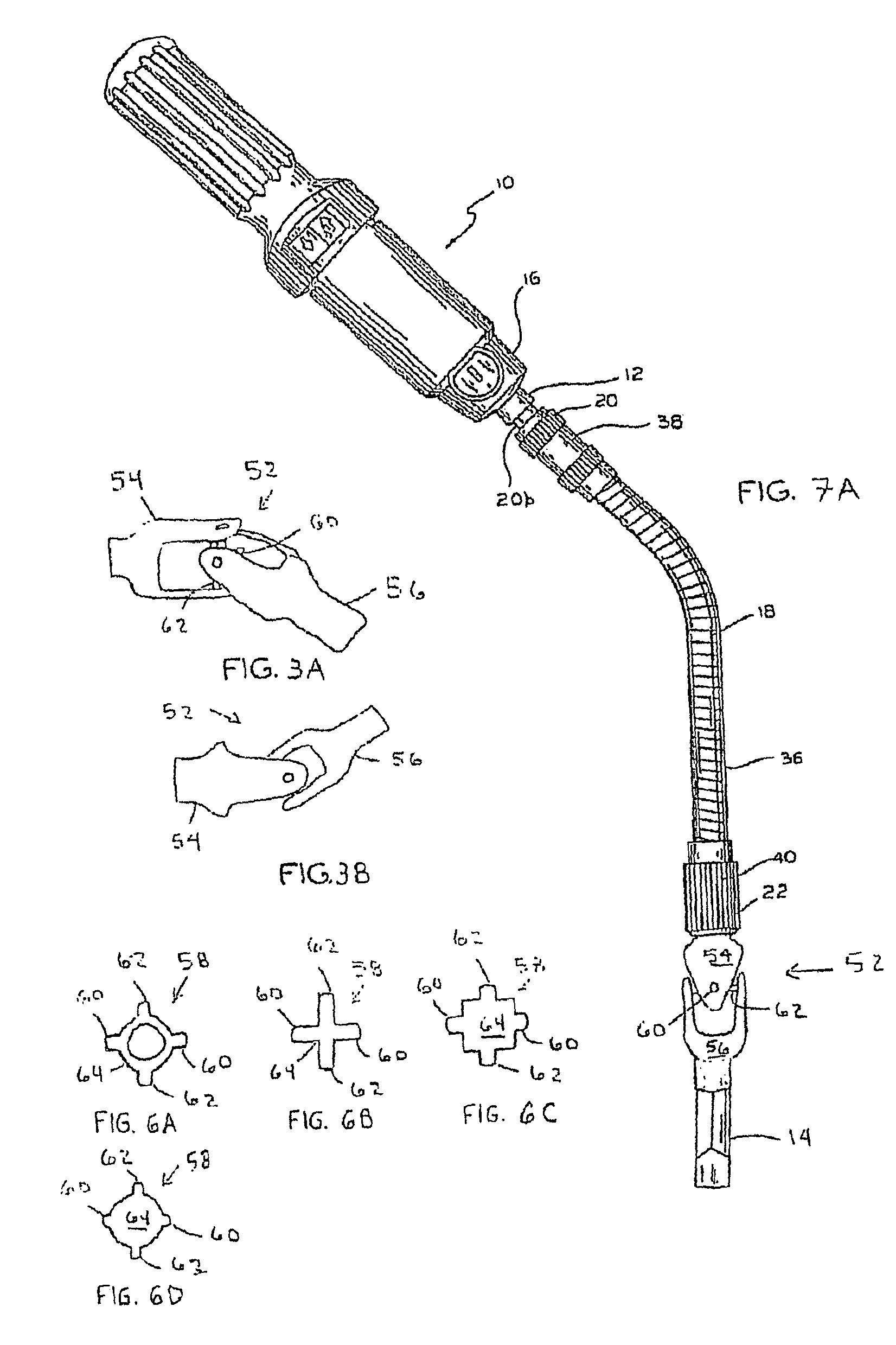
[0047]Referring to the drawings, and first to FIGS. 1 and 2, the reference numeral 10 designates generally a handheld instrument or piece of equipment, e.g., screwdriver, drill; having a chuck 12 for connection to an extension shaft 18 for rotary driven motion at one end 16 thereof. The extension shaft 18 includes a first end 20 adapted to cooperatively extend from, or attach or connect with, the chuck 12; and, a second end 22 that may similarly be adapted for attachment or extension there from and to hold a tool 14 for rotary driven motion.

[0048]The first end 20 of the ext...


PUM

PropertyMeasurementUnit
flexibleaaaaaaaaaa
range of angular movementaaaaaaaaaa
lengthaaaaaaaaaa

Abstract

A tool having a flexible extension shaft, a first end and, a second end and capable of being bent about its axis. The tool transfers rotary motion from a device to an implement. Both of the ends may be capable of independently being bent about the axis. The shaft may include a male member and a female member for a kit. Further, one end of the tool may include a rotatable member having a first and second implement.

Description

RELATED APPLICATIONS[0001]This application is a continuation-in-part of U.S. Ser. No. 12 / 908,443 filed on Oct. 20, 2010 which is a continuation of U.S. Ser. No. 12 / 284,156, filed on Sep. 18, 2008, the contents of both of which are incorporated herein by reference.FIELD OF THE INVENTION[0002]The present invention generally relates to an extension shaft capable of holding a variety of tools to be rotary driven by a handheld instrument; and more particularly, to providing an extension shaft with an increased range of angular movement of the tool with respect to the handheld instrument.BACKGROUND OF THE INVENTION[0003]A handheld instrument capable of being used with multiple types of tools—e.g., drill bits, screwdriver bits, sockets, etc. in standard and metric dimensions—is very popular because it provides a user with the ability to readily adapt the handheld instrument among a variety of workplace needs without requiring the user to carry along an extensive set of individually dedicat...

Claims


Application Information

Patent Timeline
Patent Type & Authority Patents(United States)
IPC IPC(8): B25B23/16B23B45/00B25B23/00B25G1/02B25G1/04
CPCB23B45/005B25B23/0014B25G1/025B25G1/043B25B23/0028B25B23/0021
Inventor KOZAK, BURT
Owner EAZYPOWER CORP
Why Eureka
Try Eureka