
Battery changing battery box charging method system

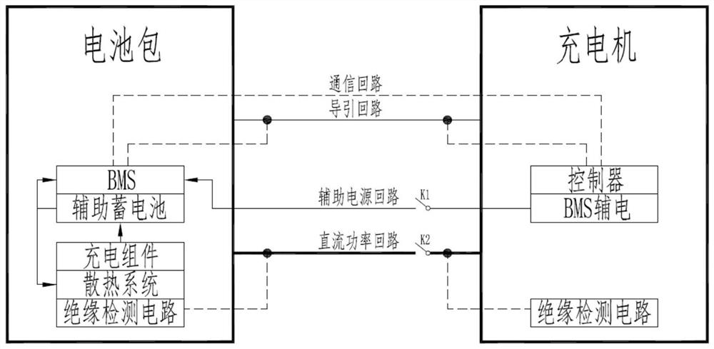
A charging method and charging system technology, which are applied in the field of car charging pile charging, can solve the problem of inability to extract battery pack voltage information, etc., and achieve the effect of facilitating lightweight design, efficient charging and battery swapping operations, and optimizing resource allocation

Active Publication Date: 2021-03-16
SGCC SMART ENERGY & ELECTRIC TRANSPORTATION TECH INNOVATION CENT (SUZHOU) CO LTD +2
View PDF7 Cites 2 Cited by
  • Summary
  • Abstract
  • Description
  • Claims
  • Application Information

AI Technical Summary

Problems solved by technology

In the above scheme, once the charging is finished, the charger cannot extract the voltage information of the battery pack.

Method used


Image

  • Battery changing battery box charging method system
  • Battery changing battery box charging method system
  • Battery changing battery box charging method system

Examples


Embodiment

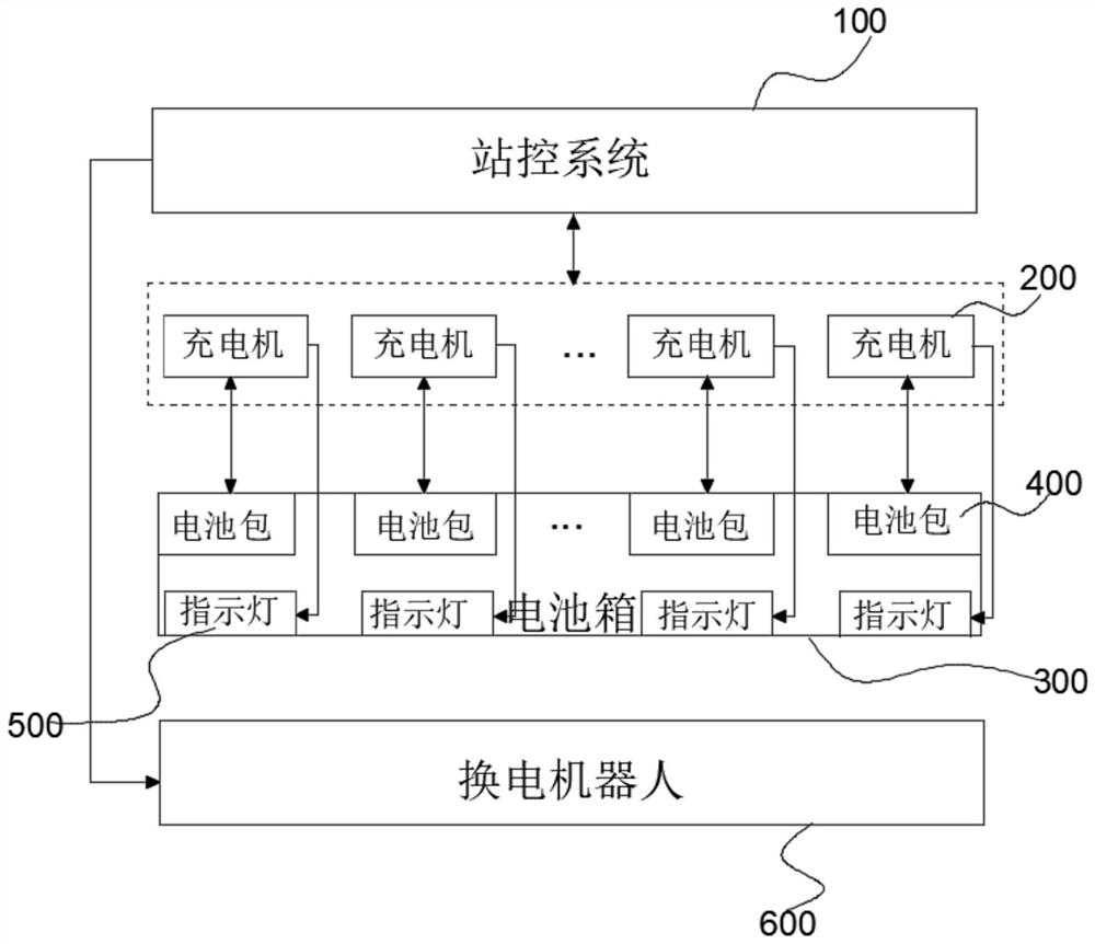
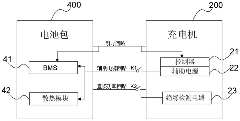
[0039] See attached Figure 2-3 As shown, a battery swapping battery box 300 charging system of the present invention includes a station control system 100 , several chargers 200 , a battery box 300 and a battery swapping robot 600 . The battery box 300 is provided with a charging position corresponding to the charger 200, the battery pack 400 is stored in the charging position, the battery exchange robot 600 is connected to the station control system 100 by communication, and the battery exchange robot 600 is used for The battery pack 400 is inserted into or removed from the battery case 300 . The charger 200 charges the battery pack 400 and communicates with the battery pack 400 , and the charger 200 and the battery pack 400 conduct guidance, energy transmission and information interaction. The station control system 100 is communicatively connected with the charger 200, the station control system 100 receives the feedback information from the charger 200 and sends an opera...

Embodiment 2

[0047] See attached Figure 4-5 , a method for charging battery pack 300 in the present invention, comprising the following steps,

[0048] Step 1. The station control system 100 gives instructions to the battery swapping robot 600, and the battery swapping robot 600 inserts the battery pack 400 that has lost power into the vacant charging compartment of the battery box 300.

[0049] Step 2. The station control system 100 issues an instruction to start charging to the charger 200. The charger 200 controls the auxiliary electrical circuit to conduct, and supplies power to the BMS 41 and the cooling module 42 in the battery pack 400 through the auxiliary power supply 22 in the charger 200.

[0050] Step 3. The charger 200 and the BMS 41 respectively detect whether the guiding circuit connecting the two is conducting, and if it is normal, execute step 4; otherwise, execute step 5.

[0051] Step 4. The charger 200 starts communication with the BMS 41, starts charging, and collect...


PUM


Abstract

The invention discloses a battery changing battery box charging system which comprises a station control system, a plurality of chargers and a battery box, charging bins corresponding to the chargersare arranged in the battery box, battery packs are stored in the charging bins, the chargers charge the battery packs and are in communication connection with the battery packs, the station control system is in communication connection with the chargers, and the station control system receives feedback information of the chargers and issues an operation instruction to the chargers. A controller, an auxiliary power supply and an insulation detection circuit are arranged in each charger, and the auxiliary power supply and the insulation detection circuit are in communication connection with thecontroller; a BMS and a heat dissipation module are arranged in each battery pack; the auxiliary power supplies supply power to the BMSs and the heat dissipation modules through auxiliary power supplyloops; the insulation detection circuits are in communication connection with the battery packs through direct-current power loops, and the insulation detection circuits are used for insulation detection in the charging process; and the controllers are in communication connection with the station control system and is communicated with the BMSs through guide loops. The invention further disclosesa charging method of the system. Lightweight design is realized, and manufacturing and operating costs are reduced.

Description

technical field [0001] The invention relates to the technical field of charging a car charging pile, in particular to a charging method and a charging system for a battery replacement box. Background technique [0002] As a rapid energy supply equipment for electric vehicles, the power station needs to store a certain number of battery packs in the station, and configure a charger to supplement the battery packs. In order to ensure the smooth progress of the charging and battery replacement process, it is necessary to perform insulation testing on the charging main circuit during the charging process, and at the same time, provide working power for the battery pack cooling module. In addition, whether charging or not, the battery pack BMS needs to be in working condition, so as to transmit the battery pack status information to the station control system in real time. At present, in order to ensure the unification of the standards for the chargers used in the power station ...

Claims


Application Information

Patent Timeline
Patent Type & Authority Applications(China)
IPC IPC(8): B60L53/80B60S5/06H01M10/42H01M10/44
CPCB60L53/80B60S5/06H01M10/44H01M10/4257H01M10/4285Y02T10/70Y02T10/7072Y02T90/16Y02E60/10Y02T90/12
Inventor 贾俊国海晓涛齐辉于士友栾永明
Owner SGCC SMART ENERGY & ELECTRIC TRANSPORTATION TECH INNOVATION CENT (SUZHOU) CO LTD
Learn More