Elevator system using a movement profile

a technology of elevator car and movement profile, which is applied in the direction of electric controllers, elevators, instruments, etc., can solve the problems of increased loss of elevator motor, increased and increased maximum speed of elevator car according to the movement profile of elevator car. , the effect of increasing the field weakening of elevator motor

Active Publication Date: 2014-07-29
KONE CORP
View PDF25 Cites 6 Cited by
  • Summary
  • Abstract
  • Description
  • Claims
  • Application Information

AI Technical Summary

Benefits of technology

[0012]In a preferred embodiment of the invention the loading of the motor drive is, in connection with an elevator system with counterweight, arranged to be limited to the limit value for the maximum permitted loading by reducing the maximum speed of the elevator car in the movement profile of the elevator car, when loaded to be heavier than the balanced load, in relation to the maximum speed of the elevator car when situated higher up and loaded in a corresponding manner. The loading of the motor drive is further arranged to be limited preferably to the limit value for the maximum permitted loading by reducing the maximum speed of the elevator car in the movement profile of the elevator car, when loaded to be lighter than the balanced load, in relation to the maximum speed of the elevator car when situated lower down and loaded in a corresponding manner.
[0014]The force acting in the elevator ropes disposed between the traction sheave and the elevator car, as also the force acting in the elevator ropes disposed between the traction sheave and the counterweight, changes when the position of the elevator car changes. This is because the weight of the elevator ropes suspended in the top part of the elevator hoistway and disposed between the traction sheave / rope pulley and the elevator car decreases when the elevator car moves upwards and increases when the elevator car moves downwards. In a corresponding manner the weight of the elevator ropes suspended in the top part of the elevator hoistway and disposed between the traction sheave / rope pulley and the counterweight increases when the elevator car moves upwards and decreases when the elevator car moves downwards. In this case, when the loading of the motor drive is limited according to the invention to the limit value for the maximum permitted loading by changing the value of a movement magnitude of the elevator car in the movement profile of the elevator car when the position of the elevator car changes, the elevator can be driven with the motor drive closer than in prior art to the upper limit for performance that is set by the maximum permitted loading of the motor drive. The torque requirement of the elevator motor and thereby the current of the electric drive of the elevator can e.g. be limited by decreasing the acceleration according to the movement profile of the elevator car when the elevator car is situated at such a point of the elevator hoistway where the torque requirement during acceleration of the elevator motor would otherwise grow to be unnecessarily large. On the other hand, the maximum speed of the elevator car according to the movement profile of the elevator car can also be increased e.g. by increasing the field weakening of the elevator motor when the elevator car is situated at such a point of the elevator hoistway where the torque requirement of the elevator motor and thereby the current requirement of the electric drive of the elevator are sufficiently small to allow supplying extra field weakening current to the elevator motor. In this way the transport capacity of the elevator can be increased and also e.g. the door-to-door time of the elevator can be shortened.
[0015]The change produced in the torque requirement of the elevator motor by the change in position of the elevator car is particularly large in those type of elevator systems in which the elevator assembly is implemented without a compensating rope, which otherwise can be used for reducing the change in the torque requirement of the elevator motor produced by a change in the weight of the elevator ropes. Other problems, however, in addition to the cost impacts, are caused in the elevator assembly by the addition of one or more compensating ropes: the compensating ropes increase the total mass to be suspended in the elevator hoistway; in addition, the compensating ropes might start to sway as a result of an earthquake and also, particularly in high-rise buildings, from the effect of wind.

Problems solved by technology

When the current increases the copper losses of the elevator motor increase; likewise, the current of the solid-state switches, such as IGBT transistors, of the frequency converter increases when the current of the elevator motor increases.
This is because overdimensioning of the frequency converter and of the elevator motor would incur extra costs; additionally, in this case the size of the frequency converter, of the elevator motor and also of any cooling apparatus possibly needed would grow to be unnecessarily large, which would hamper the placement of these devices e.g. in the elevator hoistway.

Method used


Image

  • Elevator system using a movement profile
  • Elevator system using a movement profile
  • Elevator system using a movement profile

Examples


Embodiment Construction

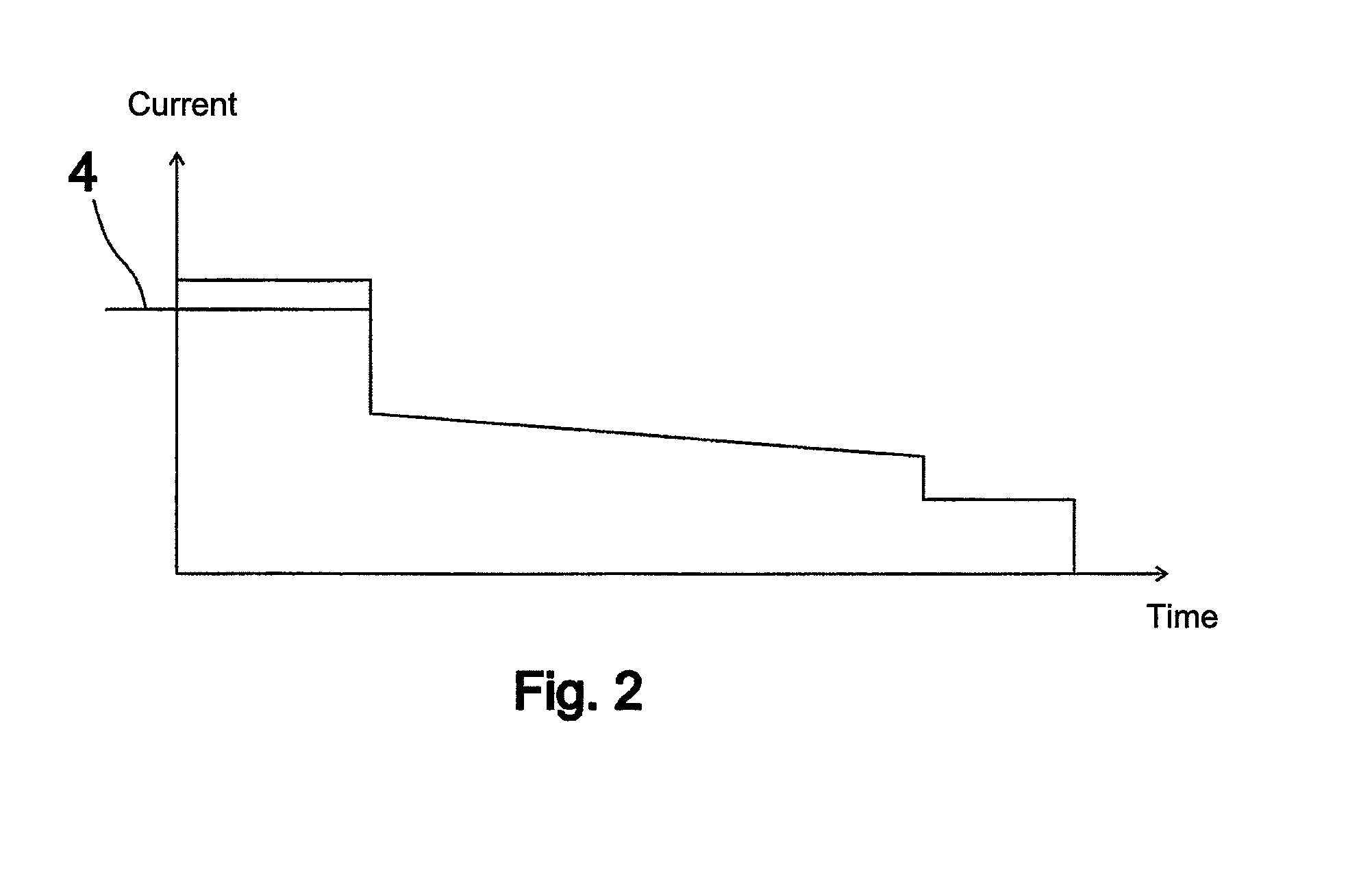
[0022]Certain features to be presented, such as changes in the speed / acceleration / deceleration and current of the elevator car can be exaggerated in the figures in order to clarify the basic idea of the invention.

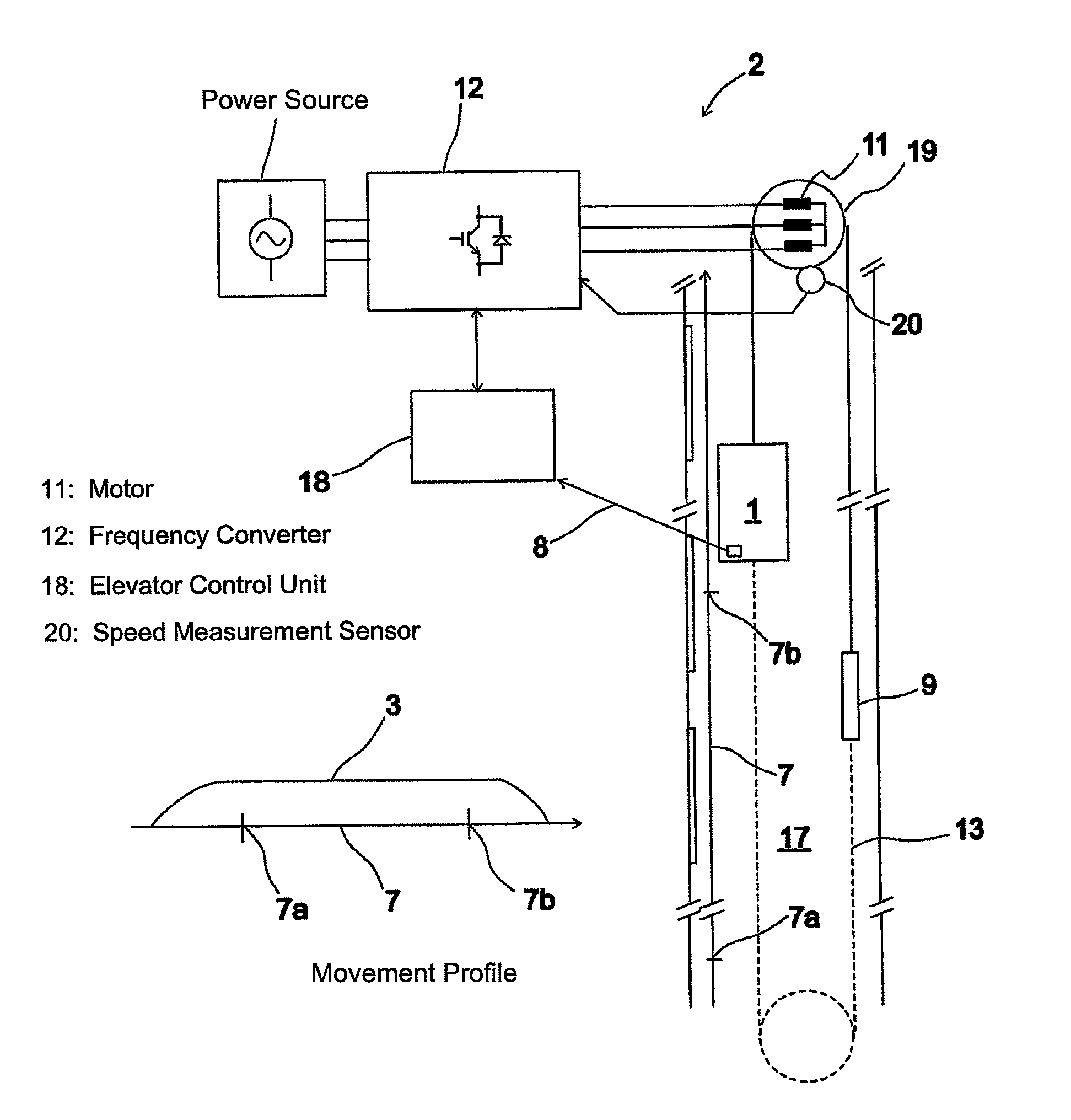
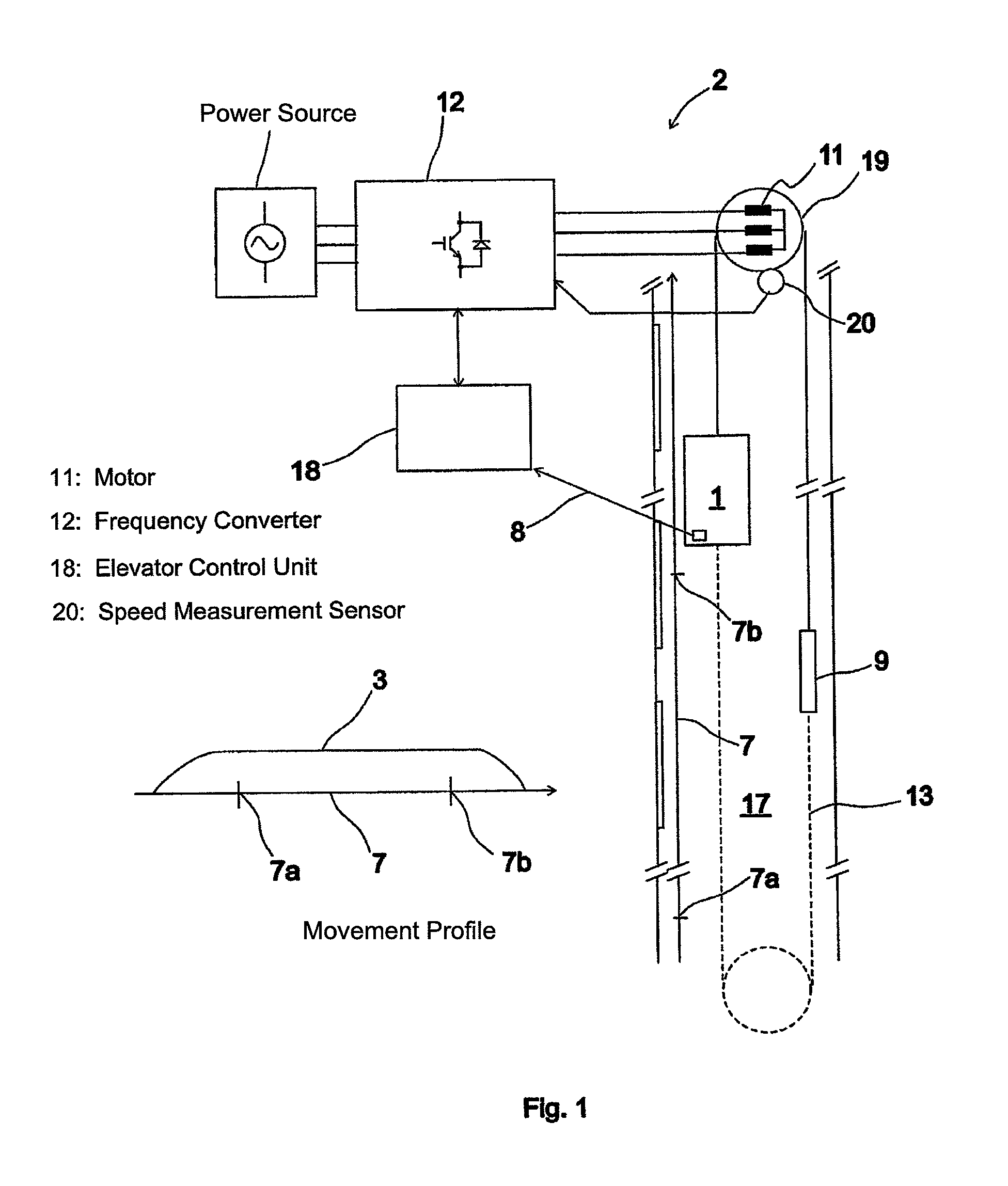
[0023]The elevator system of FIG. 1 comprises an elevator car 1 and also an electric drive 2 for moving the elevator car in the elevator hoistway 17 according to a movement profile 3 of the elevator car, which profile is formed by the elevator control unit 18. The electric drive 2 comprises a hoisting machine 19 disposed in the top part of the elevator hoistway 17, which hoisting machine comprises an alternating current motor 11 as the power producing part. In addition, the electric drive 2 comprises a frequency converter 12 for supplying variable-amplitude and variable-frequency current to the alternating current motor 11.

[0024]The elevator car 1 is suspended in the elevator hoistway 17 with suspension means, such as ropes, a belt or corresponding, passing via the traction...


PUM


Abstract

An elevator system includes an elevator car and also a motor drive for moving the elevator car according to a movement profile to be determined for the movement of the elevator car. The loading of the motor drive is arranged to be limited to the limit value for the maximum permitted loading by changing the value of a movement magnitude of the elevator car in the movement profile of the elevator car when the position of the elevator car changes.

Description

CROSS REFERENCE TO RELATED APPLICATIONS[0001]This application is a Continuation of PCT International Application No. PCT / FI2011 / 000021 filed on Apr. 13, 2011, which claims priority under 35 U.S.C. §119(a) to Patent Application No. 20105401 filed in Finland on Apr. 16, 2010, all of which are hereby expressly incorporated by reference into the present application.FIELD OF THE INVENTION[0002]The invention relates to solutions for preventing the overloading of a motor drive of an elevator system.BACKGROUND OF THE INVENTION[0003]An elevator system comprises a motor drive for moving an elevator car. The motor drive usually comprises a hoisting machine of the elevator and also a power supply apparatus, such as a frequency converter, of the hoisting machine. The elevator car is moved in the elevator hoistway e.g. with suspension ropes traveling via the traction sheave of the hoisting machine of the elevator. The elevator car and the counterweight are suspended on different sides of the trac...

Claims


Application Information

Patent Timeline
Patent Type & Authority Patents(United States)
IPC IPC(8): B66B1/28
CPCB66B1/304B66B1/30
Inventor TENHUNEN, ASMO
Owner KONE CORP
Why Eureka
Try Eureka