Methods and composition for tracking jaw motion

a technology of jaw motion and composition, applied in the field of model jaw motion, can solve the problems of inherently disrupting an individual's natural jaw movement, affecting the accuracy of impression caps, and difficult to register data obtained from frame-based systems to complete three-dimensional (“3d”) models of dentition

Inactive Publication Date: 2014-08-05
4D DENTAL SYST
View PDF23 Cites 6 Cited by
  • Summary
  • Abstract
  • Description
  • Claims
  • Application Information

AI Technical Summary

Benefits of technology

[0024]This allows the maxillary and mandibular shelled extended anatomy to be accurately registered to the corresponding upper and lower target locations at any jaw position, such as the reference position used to determine the DoF expressions. The extended anatomy may then be directly animated using the DoF expressions computed from the microsphere locations.
[0025]An object of this invention is to provide a convenient jaw tracking method that produces data that is readily registered to conventional 3D models of the dentition.

Problems solved by technology

Frame-based jaw tracking systems are cumbersome, time-consuming to setup, have limited accuracy, and their presence inherently disrupts an individual's natural jaw movement.
In addition, a significant practical limitation is that data obtained from frame-based systems are difficult to register to complete three-dimensional (“3D”) models of the dentition.
These “clutch”-based systems are limited in that they prevent a person from closing their mouth.
Additionally, the optical imaging element locations are difficult or impossible to register to the dentition.
This system requires an inconvenient calibration step using precisely measured target distances.
Another limitation of this system is the inability to register target positions to the dentition.
While jaw tracking data may be taken, target location cannot be accurately or conveniently related to the dentition due to the unknown offset of the LEDs from the teeth.
In addition, the basis for this calculation requires that a subjective correspondence be made by the user between the 3D model of the dentition and the position of the targets placed on the teeth, making this procedure difficult to execute and inaccurate.
This method also has the limitation of being unable to register the target positions to the dentition.
Target location data is not amenable to registering to the 3D surface of the teeth.
In general, the use of light emitting diodes (LEDs) as photogrammetry targets is not ideal.
Also, the computed location of such targets is inconsistent since LED devices do not emit light in a uniformly spherical manner, and therefore do not have the same optical signature in all viewing directions.
Such attachments are time consuming to fabricate, and result in target locations that are not at precisely known locations with respect to the tooth surface.
It is therefore difficult or impossible to register the computed target positions to a 3D surface model of the dentition.
This is a significant limitation, since many practical applications for jaw motion data require these data to be correlated to the full dentition
The required camera setups are large and typically immovable and are not amenable to practical clinical use.

Method used


Image

  • Methods and composition for tracking jaw motion
  • Methods and composition for tracking jaw motion
  • Methods and composition for tracking jaw motion

Examples


Embodiment Construction

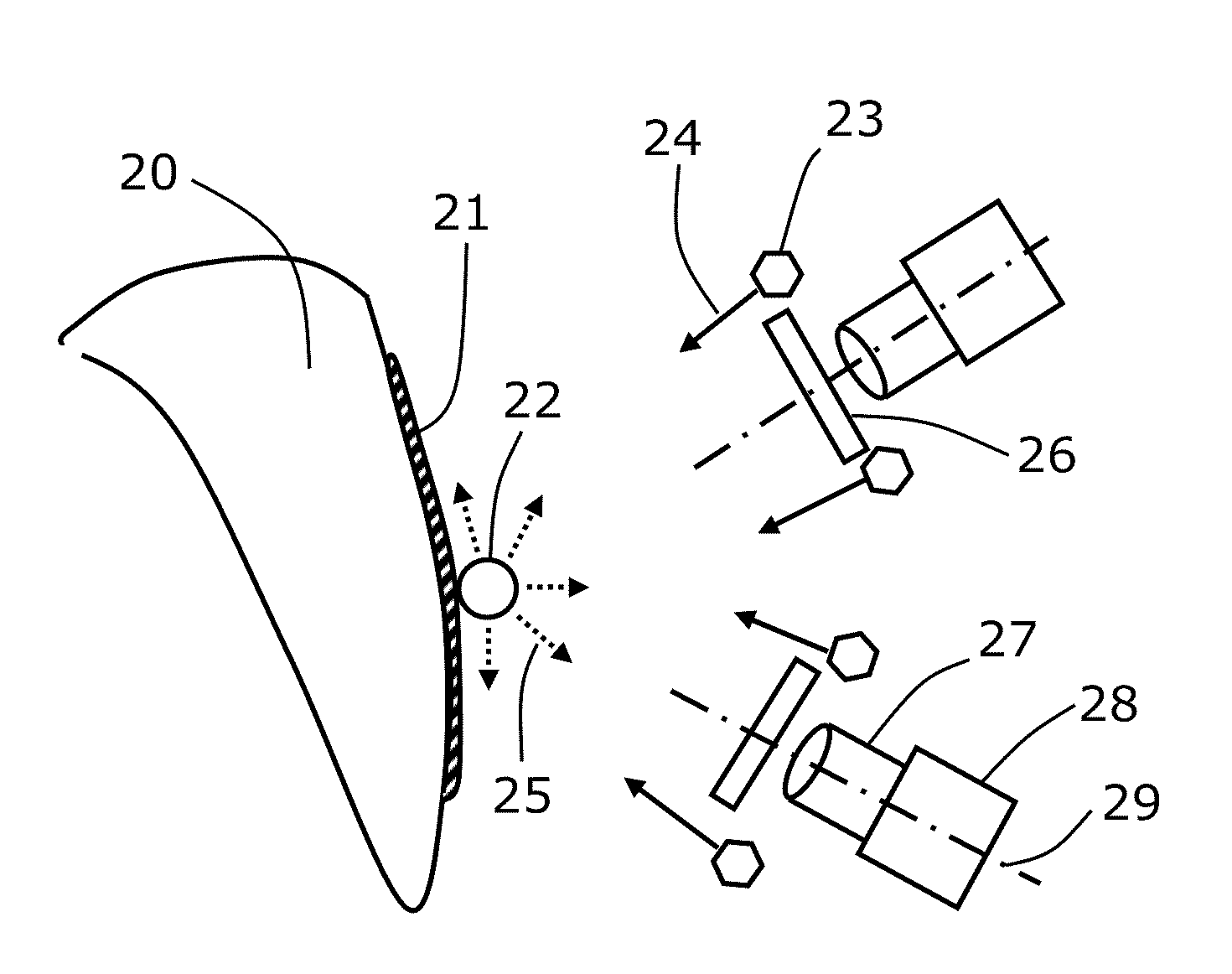
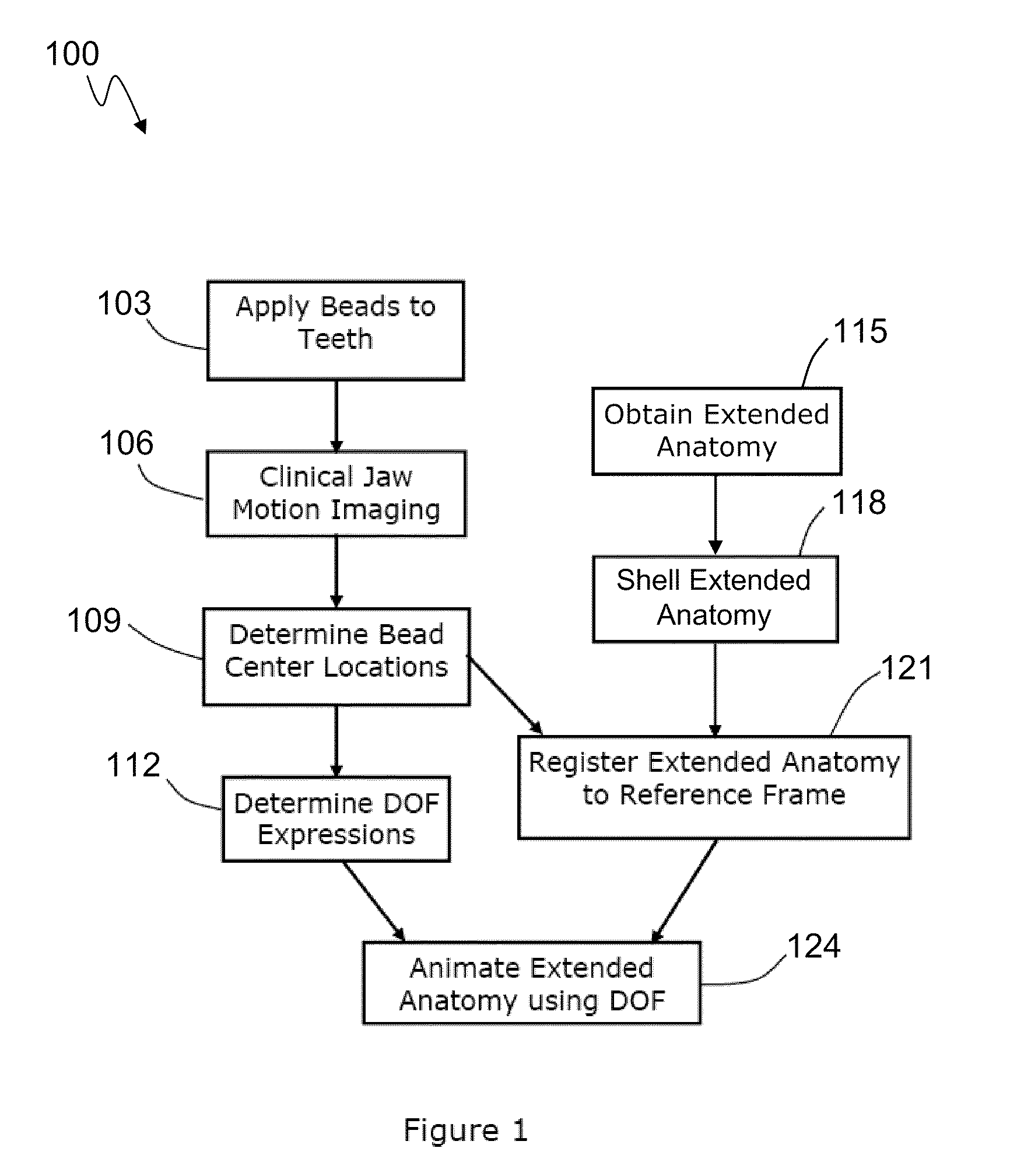
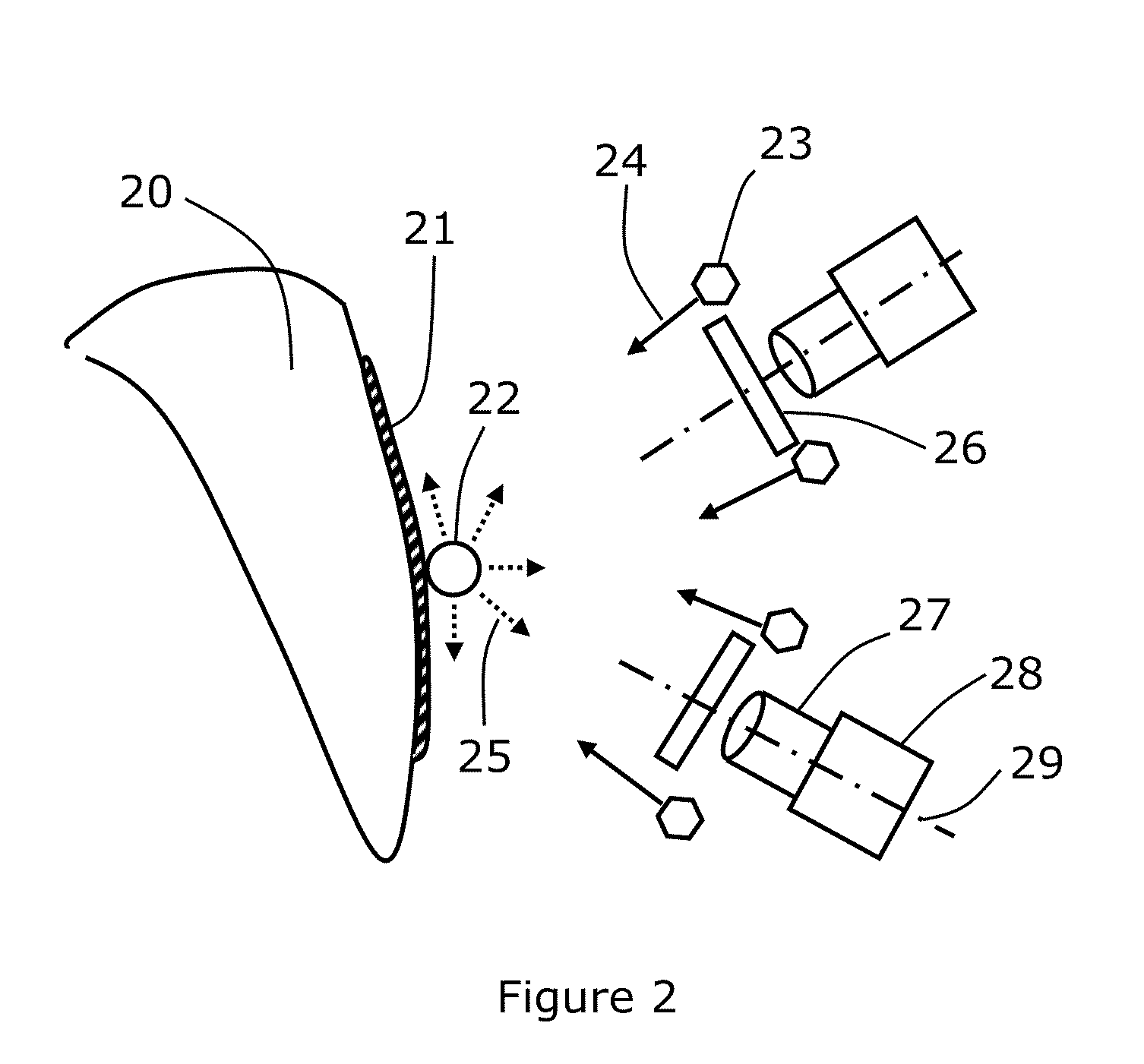
[0033]FIG. 1 depicts a method 100 according to an embodiment of the present invention in which the jaw motion of a person is tracked and digitized. Steps 103-112 describe a basic jaw tracking method, and steps 109 and 115-124 describe using of the basic tracking data to animate overlapping or extended 3D oral anatomy. A plurality of microsphere targets (such as those available from Polysciences, Inc. of Warrington, Pa.) is applied 103 to a surface of a tooth on the upper dentition of the person and a tooth surface of the lower dentition of the person. The microsphere targets may also be referred to herein as microspheres and / or beads. Any number of microsphere targets sufficient for tracking may be applied to the tooth surface in a “patch.” In a non-limiting example, each tooth surface may have 1-10 beads or more. Patches may be applied to more than one tooth in each arch (upper and / or lower) of the person. For example, a patch of microsphere targets may be applied to the surfaces o...


PUM


Abstract

In a method according to an embodiment of the present invention, a plurality of microsphere targets is applied to a surface of a tooth on the upper dentition of a person and a tooth surface of the lower dentition of the person. At least two sets of stereoscopic images are obtained, where the microsphere targets are visible in the field of view of each image. The center position of the beads is photogrammetrically determined in three dimensions for each set using the images taken from perspective positions. The change in bead positions in the sets of stereoscopic images is analyzed to mathematically characterize the jaw motion of the person.

Description

CROSS-REFERENCE TO RELATED APPLICATION[0001]This application is a continuation-in-part of U.S. application Ser. No. 12 / 435,940 filed on May 5, 2009 now abandoned, which in turn claims priority to U.S. Provisional Application No. 61 / 211,941 filed on Apr. 6, 2009 and U.S. Provisional Application No. 61 / 126,355 filed on May 5, 2008. The disclosures of all of the above applications are incorporated herein by reference.FIELD OF THE INVENTION[0002]The invention relates to the art of modeling jaw motion, and more particularly to methods for tracking jaw motion and relating the tracked motion to the oral anatomy of a person.BACKGROUND OF THE INVENTION[0003]Many methods have been employed to measure and record the movement of the human jaw, including: mechanical, electronic, ultrasonic, electromagnetic, and optical techniques. These systems generally have a physical structure (“frame”) mounted to each of the maxilla and mandible, with the relative motion between the frames being measured and...

Claims


Application Information

Patent Timeline
Patent Type & Authority Patents(United States)
IPC IPC(8): A61B5/103A61C19/04A61K6/90
CPCA61C9/0053A61C11/00
Inventor LAUREN, MARK, D.
Owner 4D DENTAL SYST
Why Eureka
Try Eureka