Shape memory alloy actuator

a memory alloy and actuator technology, applied in the direction of closed-cycle machines/engines, hot gas positive displacement engine plants, etc., can solve the problem of large distortion-restoring force generation, achieve the effect of reducing electric power consumption, suppressing an amount of heat, and improving controllability of an amount of distortion

Active Publication Date: 2014-08-12
OLYMPUS CORP
View PDF13 Cites 4 Cited by
  • Summary
  • Abstract
  • Description
  • Claims
  • Application Information

AI Technical Summary

Benefits of technology

[0027]In the shape memory alloy actuator according to the present invention, since the shape memory alloy wire portion is not exposed to an outside environment, the shape memory alloy actuator shows an effect that it is possible to make uniform a temperature change of the overall shape memory alloy wire portion and to improve controllability of an amount of distortion. Moreover, in the shape memory alloy actuator according to the present invention, since it is possible to suppress an amount of heat which is required for deformation of the shape memory alloy wire portion, the shape memory alloy actuator shows an effect that it is possible to reduce electric power consumption.

Problems solved by technology

Moreover, particularly at the time of transition (a reverse transformation) from the martensitic phase to the austenitic phase, a large distortion-restoring force is generated due to a small temperature difference.

Method used


Image

  • Shape memory alloy actuator
  • Shape memory alloy actuator
  • Shape memory alloy actuator

Examples


Embodiment Construction

[0031]An embodiment according to the present invention will be described below in detail by referring to the accompanying diagrams. However, the present invention is not restricted to the embodiment described below.

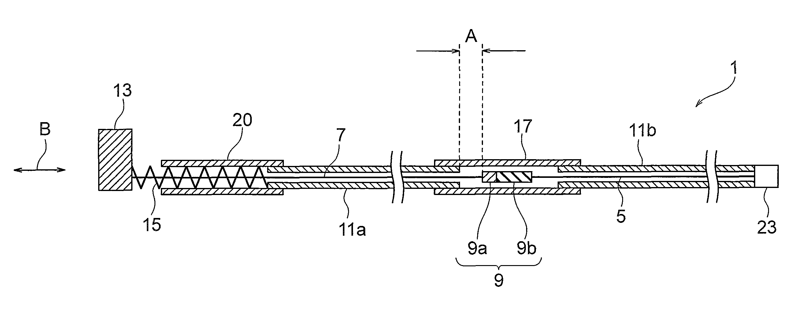
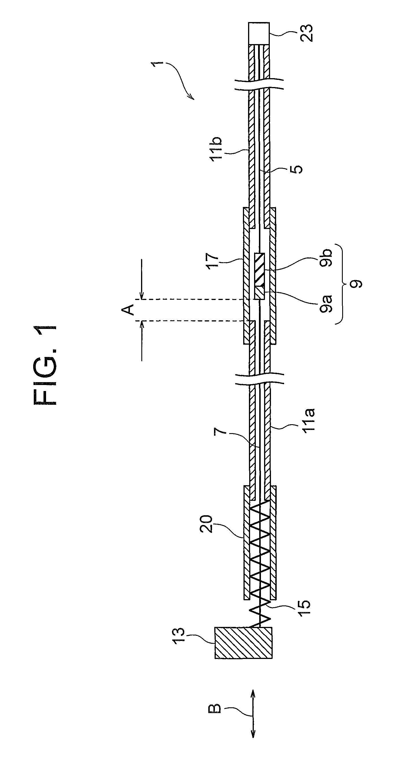
[0032]FIG. 1 is a diagram showing a cross-sectional view of a structure of a shape memory alloy actuator 1 which is the embodiment of the shape memory alloy actuator according to the present invention.

[0033]The shape memory alloy actuator 1 includes mainly, a metal wire 7, a shape memory alloy wire 5, a first tube member 11a, a second tube member 11b, a movable body 13, a bias spring 15 which is an elastic member, a fixing member 23, and a joining portion 9 which joins the metal wire 7 and the shape memory alloy wire 5.

[0034]Here, the metal wire 7 has a property of having a less deformation in a longitudinal direction.

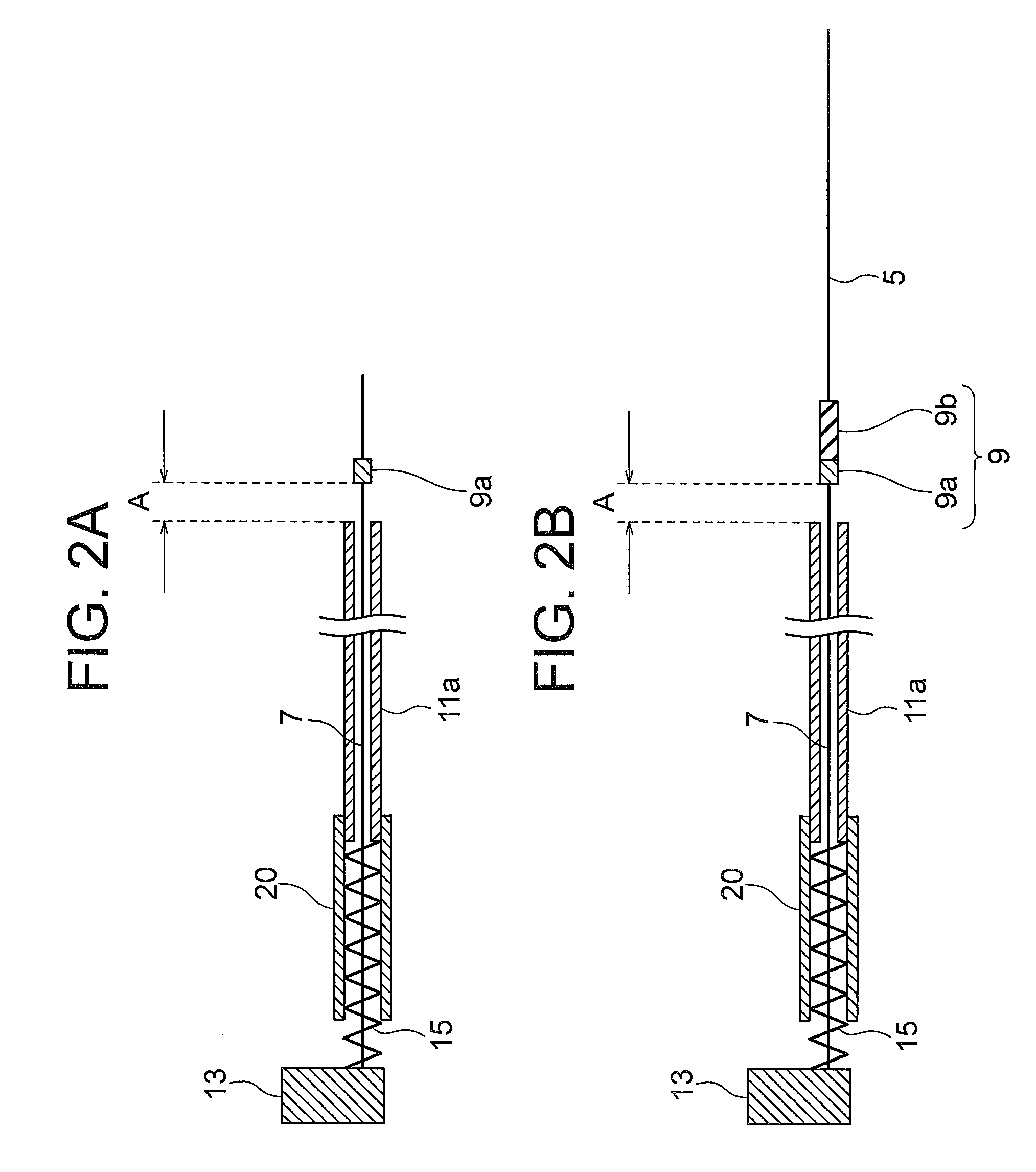
[0035]The joining portion 9 includes a first crimp terminal 9a and a second crimp terminal 9b.

[0036]One end of the second tube member 11b and one end of th...


PUM

PropertyMeasurementUnit
lengthaaaaaaaaaa
external forceaaaaaaaaaa
elongationaaaaaaaaaa

Abstract

A shape memory alloy actuator includes a wire portion which is inserted through a first tube member, a shape memory alloy wire portion which is inserted through a second tube member, a movable body which is movable in a direction in which, a length of the shape memory alloy wire portion changes, an elastic member which exerts an external force in a direction in which, the shape memory alloy wire portion elongates, and a fixing member to which, one end of the second tube member and one end of the shape memory alloy wire portion are fixed, and one end of the wire portion is connected to the movable body, and one end of the shape memory alloy wire portion and one end of the wire portion are joined to a joining portion, and the joining portion includes a plurality of crimp terminals.

Description

CROSS-REFERENCE TO RELATED APPLICATIONS[0001]The present application is based upon and claims the benefit of priority from the prior Japanese Patent Application No. 2010-196846 filed on Sep. 2, 2010; the entire contents of which are incorporated herein by reference.BACKGROUND OF THE INVENTION[0002]1. Technical Field[0003]The present invention relates to a shape memory alloy actuator.[0004]2. Description of Related Art[0005]Shape memory alloy actuators which include a shape memory alloy have hitherto been used.[0006]In a shape memory alloy, there are two states namely, an austenitic phase and a martensitic phase, and when a temperature is low, the state changes to the martensitic phase, and when the temperature is high, the state changes to the austenitic phase. Moreover, particularly at the time of transition (a reverse transformation) from the martensitic phase to the austenitic phase, a large distortion-restoring force is generated due to a small temperature difference. An actuato...

Claims


Application Information

Patent Timeline
Patent Type & Authority Patents(United States)
IPC IPC(8): F03G7/06
CPCF03G7/065
Inventor TAKAHASHI, MASAYA
Owner OLYMPUS CORP
Why Eureka
Try Eureka