
Exhaust gas cleaning device, exhaust system and clamp connection

a technology of exhaust gas and cleaning device, which is applied in the direction of fluid pressure sealing joints, flanged joints, and devices, etc., can solve the problems of manufacturing tolerances, housing sections, and the filter may become gradually clogged by noncombustible residues, and achieve low cost, narrow tolerances, and low cost

Active Publication Date: 2014-08-12
EBERSPACHER EXHAUST TECH GMBH & CO KG
View PDF15 Cites 0 Cited by
  • Summary
  • Abstract
  • Description
  • Claims
  • Application Information

AI Technical Summary

Benefits of technology

The present invention provides an exhaust gas cleaning device or an exhaust system equipped with a clamp connection that is cost-effective and long-lasting. The invention includes a design with a radially outwardly projecting ring collar on each tubular body, which are in contact with a common sealing ring via a separate ring body. This design ensures a symmetrical or uniform load on the sealing ring, leading to improved sealing action and service life. The invention also includes a flat contact surface between the ring collars and the sealing ring, which reduces the load on the sealing ring and increases its service life. Additionally, the sealing ring can be protected from thermal load by a protecting ring.

Problems solved by technology

For example, particle filters may become gradually clogged by noncombustible residues.
The relatively great manufacturing tolerances of the particular clamp, on the one hand, and of the housing sections to be connected thereto, on the other hand, are often problematic in such clamp connections.
However, the manufacturing tolerances frequently lead to asymmetrical loads on the seals, as a result of which these may become leaky over time.
Undesirable pollutant emissions into the environment as well as excessive thermal loads on adjacent components may occur in case of leakage.

Method used


Image

  • Exhaust gas cleaning device, exhaust system and clamp connection
  • Exhaust gas cleaning device, exhaust system and clamp connection

Examples


Embodiment Construction

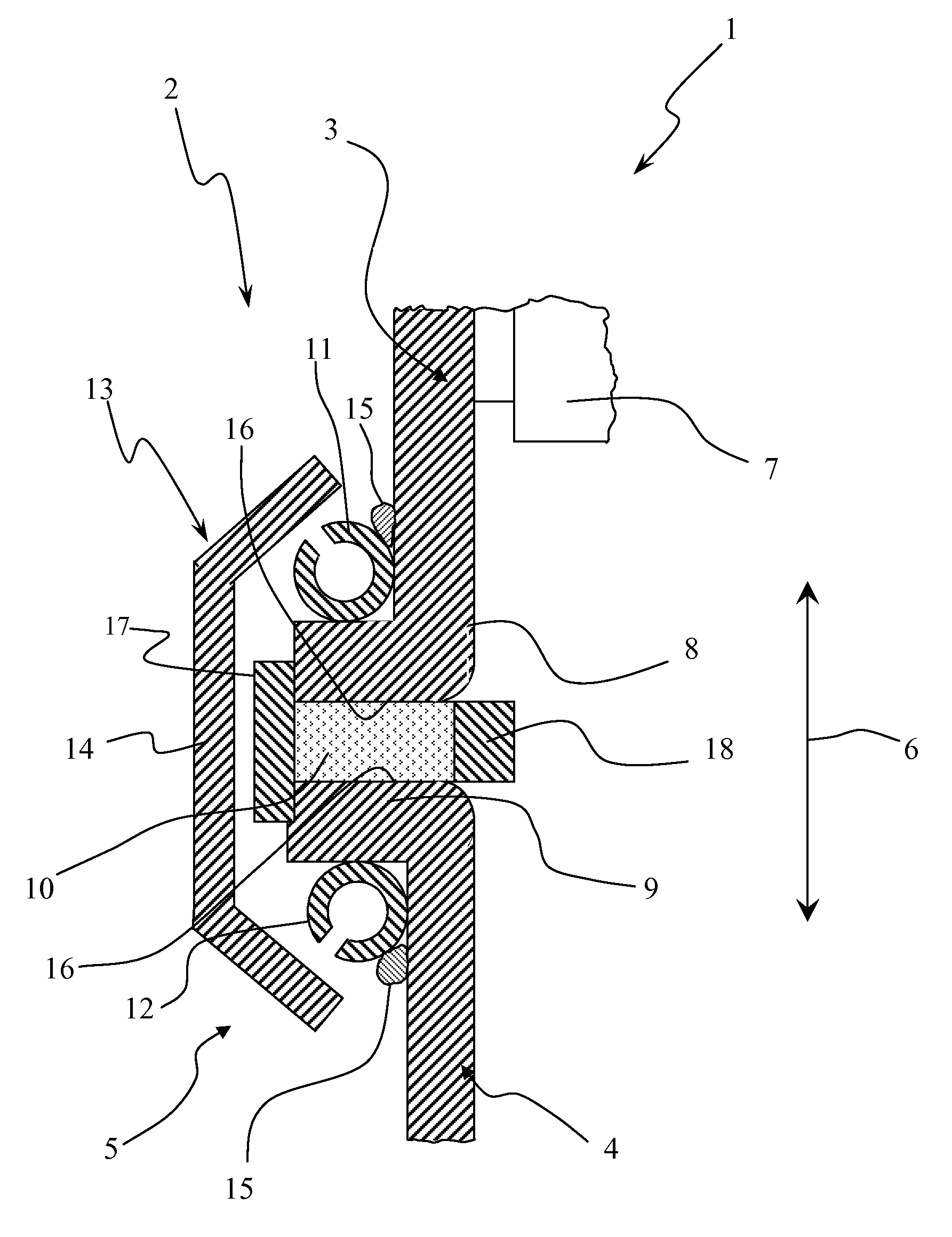
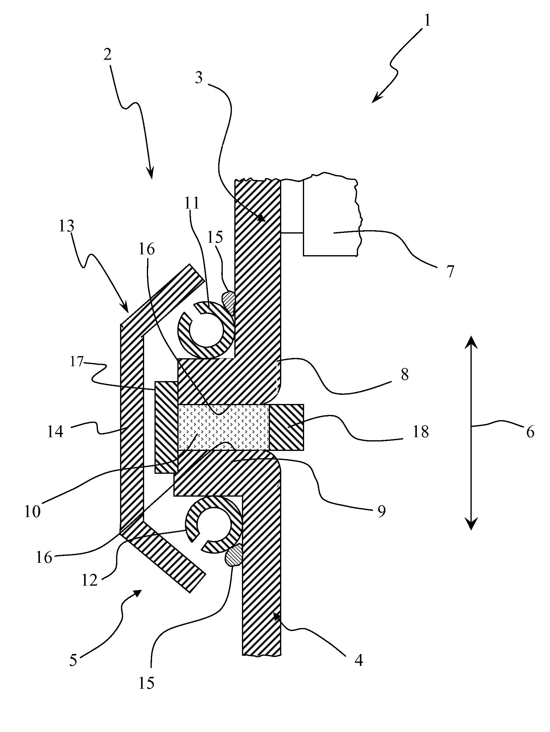
[0014]Referring to the drawing in particular, corresponding to FIG. 1, an exhaust system 1, which is shown here only partially, comprises at least one exhaust gas cleaning device 2, which is likewise shown only partially and which may be, for example, a catalytic converter or a particle filter. The exhaust system 1 is used to remove exhaust gases from an internal combustion engine, which may be arranged especially in a motor vehicle and preferably in a utility vehicle. To simplify or make possible the maintenance or replacement of at least one exhaust gas cleaning element 7 of the exhaust gas cleaning device 2 shown here only partially, at least two tubular bodies, namely, a first tubular body 3 and a second tubular body 4, are detachably connected to one another via a clamp connection 5 within the exhaust system 1 or within the exhaust gas cleaning device 2. The two tubular bodies 3, 4 extend, at least in the areas of the clamp connection 5, in parallel to a longitudinal direction ...


PUM

PropertyMeasurementUnit
temperature-aaaaaaaaaa
areaaaaaaaaaaa
temperature-resistantaaaaaaaaaa

Abstract

An exhaust gas cleaning device (2) for an exhaust system (1) of an internal combustion engine with an exhaust gas cleaning element (7), which is arranged in a first tubular body (3), and with a second tubular body (4), to which the first tubular body (3) is detachably connected via a clamp connection (5). The clamp connection (5) includes a radially outwardly projecting first ring collar (8), formed at the first tubular body (3) and extending circumferentially in a closed form and a radially outwardly projecting second ring collar (9), formed at the second tubular body (4) and extending circumferentially in a closed form. A sealing ring (10) extends circumferentially in a closed form and is axially in contact with the first ring collar (8) and the second ring collar (9). A first ring body (11) is arranged on the outside at the first tubular body (3) and is axially in contact with the first ring collar on the side facing away from the sealing ring (10). A second ring body (12) is arranged on the outside at the second tubular body (4) and is axially in contact with the second ring collar (9) on the side facing away from the sealing ring (10). A clamp (13) extends over both the first ring body and said second ring body (11, 12) and tightens these axially towards one another.

Description

CROSS REFERENCE TO RELATED APPLICATIONS[0001]This application claims the benefit of priority under 35 U.S.C. §119 of German Patent Application DE 10 2009 007 391.4 filed Feb. 5, 2009, the entire contents of which are incorporated herein by reference.FIELD OF THE INVENTION[0002]The present invention pertains to an exhaust gas cleaning device for an exhaust system of an internal combustion engine, especially of a motor vehicle. The present invention pertains, in addition, to an exhaust system equipped with such an exhaust gas cleaning device as well as to a clamp connection for use in such an exhaust system or in such an exhaust gas cleaning device.BACKGROUND OF THE INVENTION[0003]Exhaust systems of internal combustion engines usually contain a plurality of exhaust gas cleaning devices, for example, catalytic converters, particle filters and the like. It may be necessary in case of high mileages of the internal combustion engines equipped therewith to replace a cleaning element of suc...

Claims


Application Information

Patent Timeline
Patent Type & Authority Patents(United States)
IPC IPC(8): B01D50/00F16L17/00
CPCF01N13/1838F01N13/1805F01N13/1844F01N2450/18F16L23/04
Inventor DATZ, WOLFGANGKRAUSE, MICHAEL
Owner EBERSPACHER EXHAUST TECH GMBH & CO KG
Learn More