Eureka AIR delivers breakthrough ideas for toughest innovation challenges, trusted by R&D personnel around the world.

Method for detecting damage to a deck of a bridge

a bridge and damage detection technology, applied in the field of bridge damage detection, can solve problems such as cracks and fissures, damage to be escalated, and damage to occur

Inactive Publication Date: 2014-08-12
PASUKO KK
View PDF12 Cites 25 Cited by
  • Summary
  • Abstract
  • Description
  • Claims
  • Application Information

AI Technical Summary

Benefits of technology

The invention allows for indirectly monitoring the structure of the deck on the rear surface of the pavement by analyzing the thermal infrared video of the surface. This can help detect damage to the deck, like cracks, by detecting the presence of water.

Problems solved by technology

To a deck of a road bridge, there may occur damage such as cracks and fissures due to repeated loads by running vehicles on the pavement.
With such damage furthered, vicinities of damage are repeatedly displaced with load actions, causing the damage to be escalated with the result of occurrence of potholes, peeling or other damage at portions of the pavement located above the damage portion.
Thus, damage to the deck causes damage to the pavement and moreover adversely affects traffic of vehicles, making it desirable to detect any damage to the deck in early stages.
However, since the deck is covered with the pavement, it is difficult to detect any damage to the deck from the top surface side of the pavement.
In many cases, detection of any damage to the deck is not achieved until damaged pavement is removed for repairing due to occurrence of potholes or the like in the pavement.

Method used


Image

  • Method for detecting damage to a deck of a bridge
  • Method for detecting damage to a deck of a bridge
  • Method for detecting damage to a deck of a bridge

Examples


Embodiment Construction

[0045]Hereinbelow, an embodiment of the present invention will be described in detail with reference to the accompanying drawings.

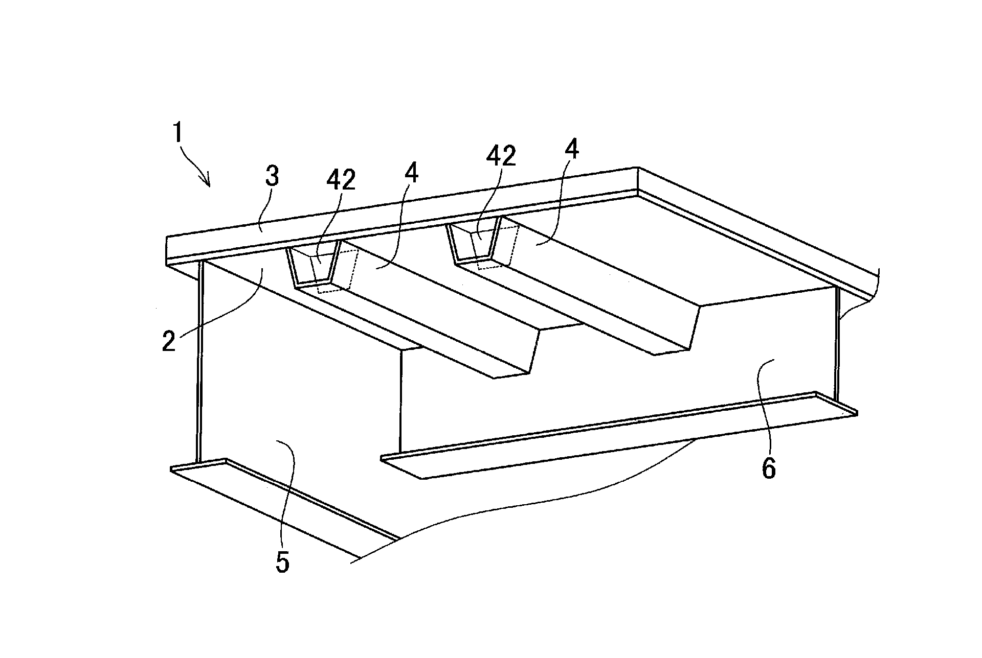
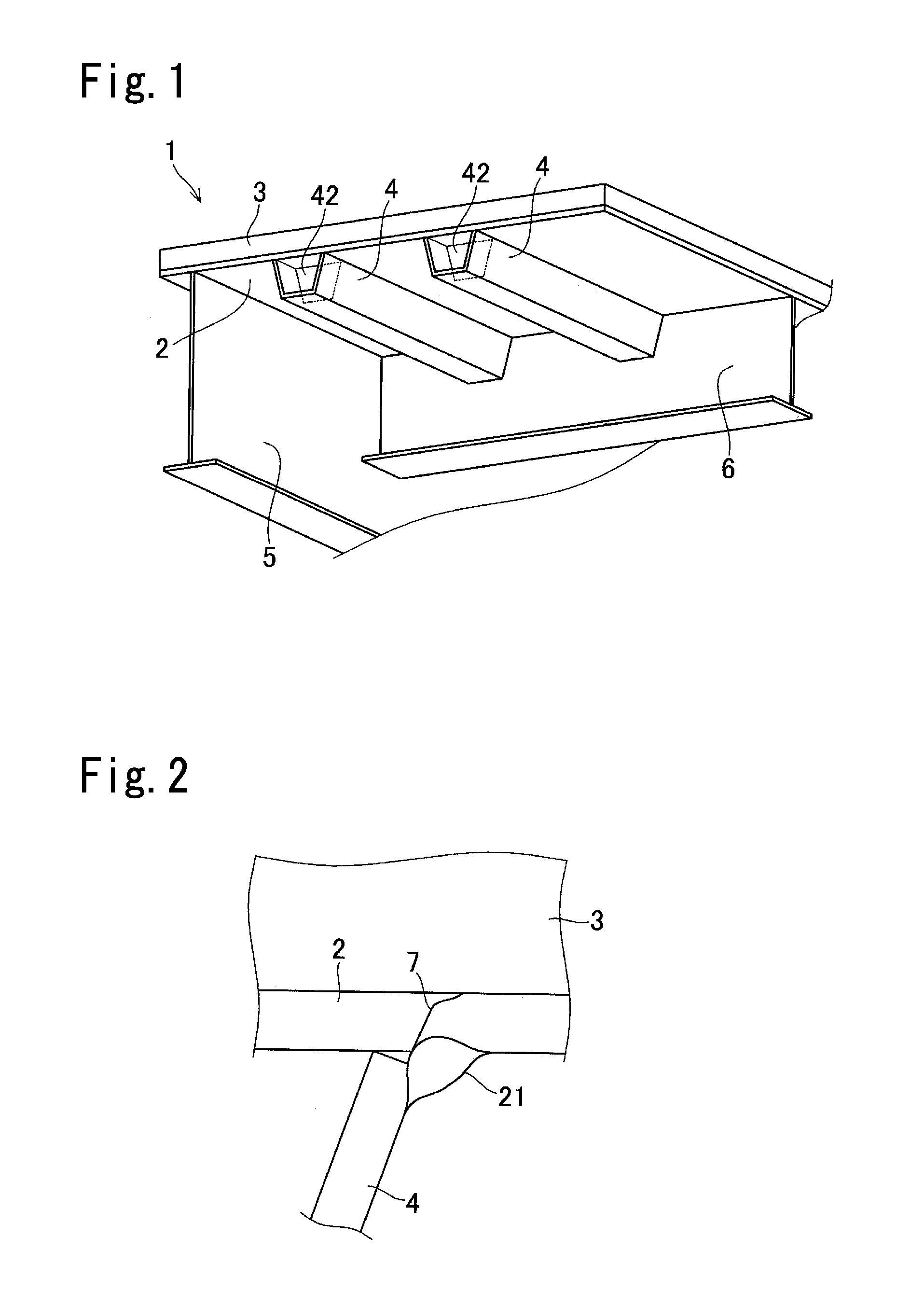
[0046]FIG. 1 is a view showing an aspect of a deck made from steel, as observed from below, as a deck to which a deck-damage detection method according to this embodiment is applied. This steel-plate deck 1 has a deck plate 2, and a pavement 3 laid on a top surface of the deck plate 2. On a lower surface of the deck plate 2, provided as reinforcing members are troughs 4 each having a U-shaped cross section and extending along a bridge-axis direction, longitudinal ribs 5 extending parallel to the troughs 4 and having an I-type cross section, and lateral ribs 6 extending along a direction orthogonal to the bridge axis. The deck plate 2, the troughs 4, the longitudinal ribs 5 and the lateral ribs 6 are in all cases formed from steel material. The troughs 4, the longitudinal ribs 5 and the lateral ribs 6 are fixed to the deck plate 2 by welding. In a weld zon...


PUM


Abstract

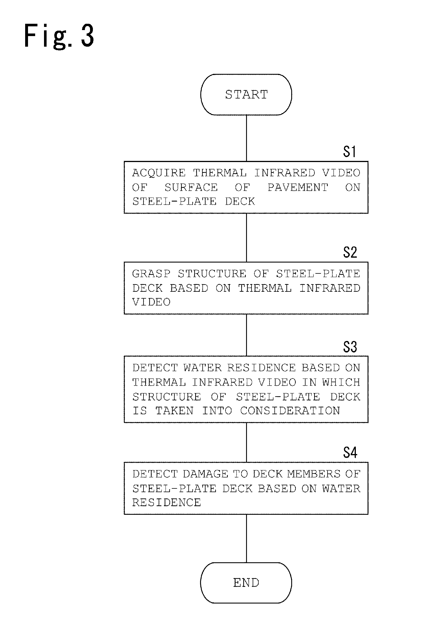
Provided is a method for detecting damage to a deck of a bridge, the method allowing detection work to be achieved with less labor and being capable of reducing the time and cost needed for the detection work. From a road-surface measuring vehicle running on pavement 3 on top of a steel-plate deck 1, a thermal infrared video of the surface of the pavement 3 is acquired by a thermal infrared video camera. Based on the thermal infrared video, troughs 4 of the steel-plate deck 1 are detected to grasp the structure of the steel-plate deck 1. Residence of water inside prescribed trough members 41 and sealing diaphragms 42 is detected from low-temperature regions R2 from among regions corresponding to troughs 4 in the thermal infrared video, and from rectangular low-temperature sections L2 that surround the regions R2. Through cracks are detected in deck plates 2 that correspond to troughs 4 in which residence of water has been detected.

Description

TECHNICAL FIELD[0001]The present invention relates to a method for detecting damage to a deck of a bridge by using a thermal infrared video captured from a surfaces side of pavement laid on a deck of a bridge, where the deck is positioned on a rear surface side of the pavement.BACKGROUND ART[0002]A bridge for roads such as viaducts of expressways (hereinafter, referred to as road bridge) is constituted, as a main structure, of bridge piers fixed on the ground, a main girder stretched between the bridge piers, a deck placed on the main girder, and pavement laid on the deck. Decks for road bridges, having a function of transferring a load of a vehicle running on the pavement to the bridge piers through the main girder, have been developed in various types, including RC decks formed from reinforced concrete, steel floor systems formed from steel material, composite decks formed from reinforced concrete and steel material, and the like.[0003]To a deck of a road bridge, there may occur d...

Claims


Application Information

Patent Timeline
Patent Type & Authority Patents(United States)
IPC IPC(8): H04N5/33H04N7/18
CPCE01D22/00G01J5/0022G01J2005/0077G01N25/72G01N33/42
Inventor UCHIMA, MITSUAKIKUROSU, HIDEAKIMAEDA, CHIKAKUNIYAMAGAMI, TETSUJITSUKAMOTO, SHIGEAKI
Owner PASUKO KK
Why Eureka
Eureka Blog
Learn More