Method and system for detecting damage to components of an aircraft

a technology for aircraft and components, applied in the direction of instruments, measurement of fluid loss/gain rate, transportation and packaging, etc., can solve problems such as decompression of a pressurized area of aircra

Active Publication Date: 2017-09-14
AIRBUS OPERATIONS GMBH
View PDF0 Cites 2 Cited by
  • Summary
  • Abstract
  • Description
  • Claims
  • Application Information

AI Technical Summary

Benefits of technology

[0004]The invention addresses an object of specifying a method and a system that make it possible to detect, in a simple manner, damage t

Problems solved by technology

In long-term operation of an aircraft, cracks occurring in structural members of the aircraft as a result of material fatigue, for example, and dam

Method used


Image

  • Method and system for detecting damage to components of an aircraft
  • Method and system for detecting damage to components of an aircraft
  • Method and system for detecting damage to components of an aircraft

Examples


first embodiment

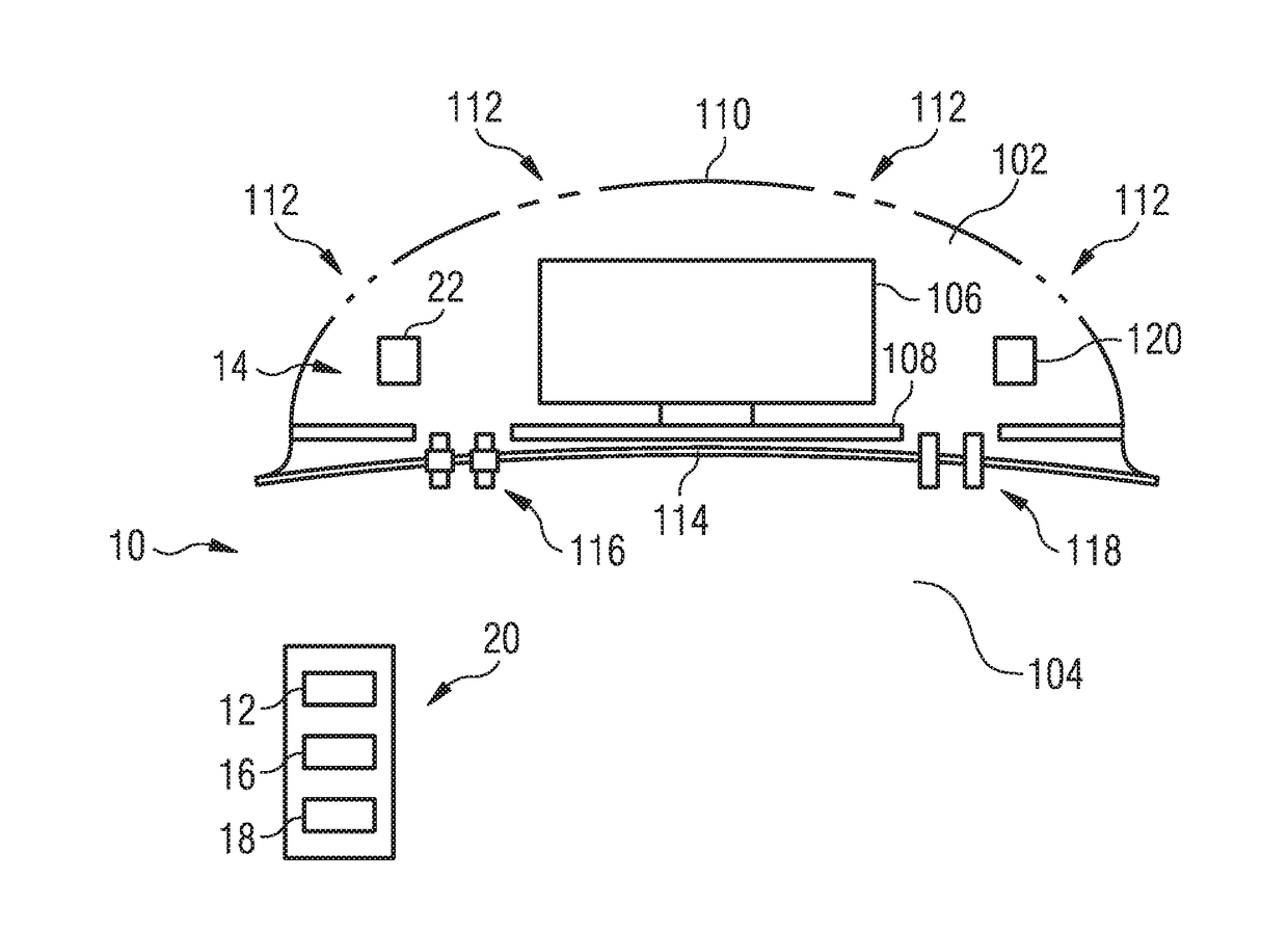
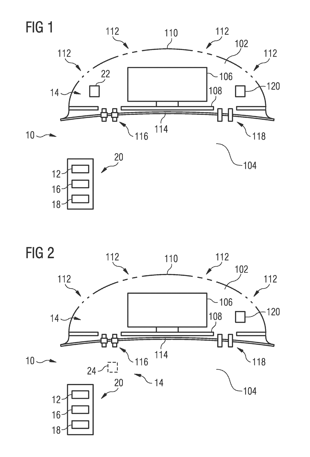
[0044]In the system 10 shown in FIG. 1, the recording device 14 comprises a first absolute pressure sensor 22 arranged in the unpressurized first area 102, which sensor measures the actual pressure pactual1 in the unpressurized first area 102. The measured value recorded by the first absolute pressure sensor 22 and characteristic of the actual pressure pactual1 in the unpressurized first area 102 is transmitted to the comparison device 16 as actual pressure parameter. The comparison device 16 also receives from the determination device 12 as a theoretical pressure parameter the theoretical pressure ptheo1 in the unpressurized first area 102, which is determined by the determination device 12 on the basis of a measured flight altitude of the aircraft. The altitude of the aircraft is measured by a GPS system 120, which is provided anyway in the unpressurized first area 102 in the form of a radome.

[0045]The comparison device 16 compares the theoretical pressure parameter transmitted to...

second embodiment

[0046]the system 10 illustrated in FIG. 2 differs from the arrangement shown in FIG. 1 in that, instead of a first absolute pressure sensor arranged in the unpressurized first area 102, the recording device 14 comprises a second absolute pressure sensor 24, which is arranged in the pressurized second area 104 and measures the actual pressure pactual2 in the pressurized second area 104. The measured value recorded by the second absolute pressure sensor 24 and characteristic of the actual pressure pactual2 in the pressurized second area 104 is transmitted as an actual pressure parameter to the comparison device 16. The comparison device 16 further receives from the determination device 12 as a theoretical pressure parameter the theoretical pressure ptheo2 in the pressurized second area 104, which is determined by the determination device 12, taking account of the flight altitude of the aircraft measured by the GPS system 120, on the basis of altitude-dependent reference values for the...

third embodiment

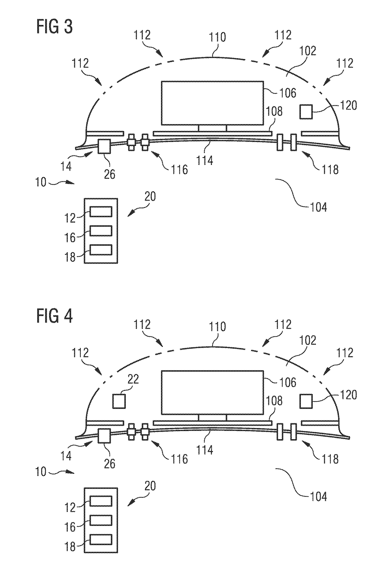
[0048]the system 10 illustrated in FIG. 3 differs from the arrangement shown in FIG. 1 in that, instead of a first absolute pressure sensor arranged in the unpressurized first area 102, the recording device 14 comprises a differential pressure sensor 26. The differential pressure sensor 26 is arranged in the region of the partition wall 114 provided between the unpressurized first area 102 and the pressurized second area 104 and measures the actual pressure difference Δpactual between the unpressurized first area 102 and the pressurized second area 104. The measured value recorded by the differential pressure sensor 26 and characteristic of the actual pressure difference Δpactual between the unpressurized first area 102 and the pressurized second area 104 is transmitted as an actual pressure parameter to the comparison device 16. The comparison device 16 further receives from the determination device 12 as a theoretical pressure parameter the theoretical pressure difference Δptheo b...


PUM


Abstract

In a method for detecting damage to a component of an aircraft, having an unpressurized first area and a pressurized second area, at least one theoretical pressure parameter, characteristic of a theoretical pressure in the unpressurized first area, a theoretical pressure in the pressurized second area or a theoretical pressure difference between the unpressurized first area and the pressurized second area, is determined. At least one actual pressure parameter, characteristic of an actual pressure in the unpressurized first area, an actual pressure in the pressurized second area or an actual pressure difference between the unpressurized first area and the pressurized second area, is recorded. The theoretical pressure parameter is compared with the actual pressure parameter. Damage to a component of the aircraft causing a compression of the unpressurized first area is detected when a difference between the theoretical pressure parameter and the actual pressure parameter exceeds a threshold value.

Description

CROSS-REFERENCES TO RELATED APPLICATIONS[0001]This application claims the benefit of the German patent application No. 10 2016 204 038.3 filed on Mar. 11, 2016, the entire disclosures of which are incorporated herein by way of reference.BACKGROUND OF THE INVENTION[0002]The invention relates to a method and a system for detecting damage to components of an aircraft.[0003]In long-term operation of an aircraft, cracks occurring in structural members of the aircraft as a result of material fatigue, for example, and damage to components such as connecting elements, cable ducts or seals, for example, can lead to a decompression of a pressurized area of the aircraft. In particular, pressure equalization processes can take place between pressurized and unpressurized aircraft areas. For example, air from a passenger cabin, which is maintained at an increased pressure relative to the ambient pressure at the flight altitude of the aircraft when in flight mode of the aircraft, can flow into a r...

Claims


Application Information

Patent Timeline
IPC IPC(8): B64D45/00G07C5/08
CPCB64D45/00B64D2045/0085G07C5/0808G01M3/26G01M5/0033G01M17/00G01M5/00
Inventor SCHAUPMANN, CHRISTIANKOSUBEK, JENS
Owner AIRBUS OPERATIONS GMBH
Why Eureka
Try Eureka