Manufacturing method of a glass blank for magnetic disk and manufacturing method of a glass substrate for magnetic disk

a manufacturing method and technology for glass substrates, applied in glass rolling apparatus, glass tempering equipment, manufacturing tools, etc., can solve problems such as troublesome head crush or thermal asperity, deep cracks may be generated on the surface of sheet glass materials, and the flatness of formed sheet glass materials is not achieved

Inactive Publication Date: 2014-08-19
HOYA CORP
View PDF15 Cites 6 Cited by
  • Summary
  • Abstract
  • Description
  • Claims
  • Application Information

AI Technical Summary

Benefits of technology

[0023]Preferably, the manufacturing method of a glass blank for magnetic disk may further includes cutting process for cutting molten glass with cutting blades. The temperature adjusting process may heat a cut mark that is formed with the cutting blades in the cutting process.

Problems solved by technology

The shortened floating distance of the magnetic head may easily cause a head crush trouble or a thermal asperity trouble.
The sheet glass material is easy to warp, and therefore good flatness of the formed sheet glass material is not achieved.
However, when the removal stock is increased in the grinding process, a deep crack may be generated in the surface of the sheet glass material.
However, when the removal stock is increased in the polishing process in which the loose abrasive grains and the resin polisher are used, the neighborhood in the outer circumferential edge portion is rounded in the principal surface of the sheet glass material to cause a “roll-off problem” of the edge portion.
As a result, the recording and reading operations of the magnetic head are not precisely performed in the magnetic layer in the neighborhood of the outer circumferential edge portion.
This is the “roll-off problem”.
When the removal stock is increased in the polishing process, a time necessary for the polishing process is unfavorably lengthened.
Even if grinding, for example, is performed to such glass material, removal stock becomes uneven on the machined surface, and degree of parallelization cannot be therefore improved.
Further, there is a problem that defect which originates from the glass material remains, or that flatness of the glass material becomes even worse.
Then, there is also a problem that the cut mark still remains as a defect in the machined glass substrate for magnetic disk.

Method used


Image

  • Manufacturing method of a glass blank for magnetic disk and manufacturing method of a glass substrate for magnetic disk
  • Manufacturing method of a glass blank for magnetic disk and manufacturing method of a glass substrate for magnetic disk
  • Manufacturing method of a glass blank for magnetic disk and manufacturing method of a glass substrate for magnetic disk

Examples


first embodiment

[0063]A manufacturing method of a glass substrate for magnetic disk according to the present invention will be described in detail below.

(Magnetic Disk and Glass Substrate for Magnetic Disk)

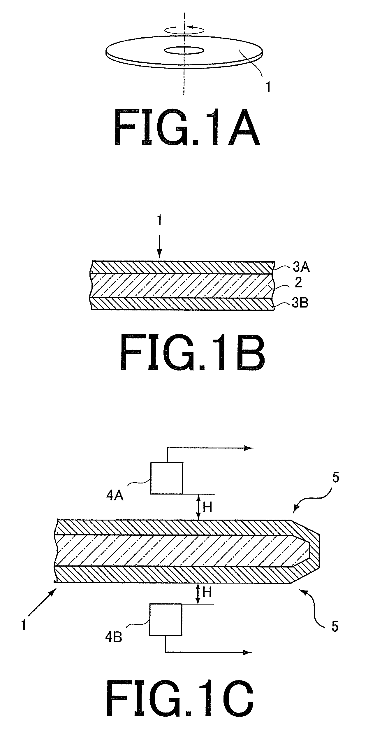
[0064]Referring now to FIGS. 1A to FIG. 1C, a magnetic disk manufactured using a glass substrate for magnetic disk will be explained. FIG. 1A is a view illustrating a magnetic disk prepared using a glass substrate for magnetic disk according to an embodiment of the invention. FIG. 1B is a view illustrating a section of the magnetic disk. FIG. 1C is a view illustrating an arrangement in which a magnetic head is floated above the surface of the magnetic disk.

[0065]As illustrated in FIG. 1A, a magnetic disk 1 is a ring-shaped, and is driven around its axis of rotation. As illustrated in FIG. 1B, the magnetic disk 1 has a glass substrate 2 and at least magnetic layers 3A, 3B.

[0066]Note that, except the magnetic layers 3A, 3B, although not illustrated, an adhesive layer, a soft magnetic layer, a non-m...

second embodiment

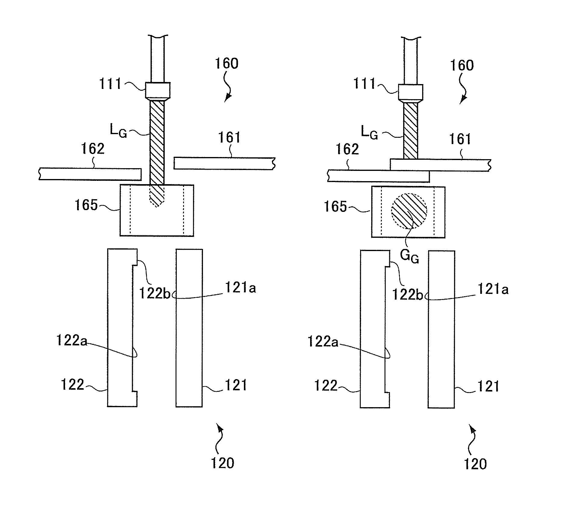
[0146]Next, a manufacturing method of a glass substrate for magnetic disk according to the second embodiment will be described. The manufacturing method of a glass substrate for magnetic disk according to the present embodiment is different from the first embodiment in a press forming process. The other processes are the same as those described in the first embodiment, and explanations of the other processes are therefore omitted. The part different from the first embodiment will be explained.

[0147]Unlike the first embodiment, the heating section 165 is not provided around the cutting unit 160 in the present embodiment. Further, unlike the first embodiment, a holding section 180 is provided between the cutting unit 160 and the pressing unit 120 in the present embodiment.

[0148]Here, with reference to the side views illustrated in FIGS. 7A to 7C, the press forming process in the present embodiment will be explained. FIG. 7A is a side view illustrating an arrangement before the molten ...

examples

[0170]Simulations and experimental results will be explained below to verify the effect of the present inventions with reference to Examples and Comparative Examples.


PUM

PropertyMeasurementUnit
viscosityaaaaaaaaaa
thicknessaaaaaaaaaa
distanceaaaaaaaaaa

Abstract

A manufacturing method of a glass blank for magnetic disk including a pair of principal surfaces, the method including: dropping process for dropping a lump of molten glass; pressing process for forming a sheet glass material by sandwiching simultaneously the lump from both sides of the dropping path of the lump with surfaces of the pair of dies facing together, and performing press forming to the lump; and temperature adjusting process for adjusting temperature of the lump before the pressing process such that viscosity variation of the lump is reduced with respect to positions over the entirety of the lump in the pressing process.

Description

CROSS-REFERENCE TO RELATED APPLICATION[0001]This application is based upon and claims the benefit of priority of U.S. Provisional Application No. 61 / 444,405 filed in the US Patent and Trademark Office on Feb. 18, 2011, the entire contents of which are incorporated herein by reference.FIELD[0002]The present invention relates to a manufacturing method of a glass substrate for magnetic disk and a glass blank for magnetic disk having a pair of principal surfaces.BACKGROUND[0003]Recently, a hard disk device is incorporated in a personal computer, a notebook personal computer, and a DVD (Digital Versatile Disc) recording apparatus in order to record data. Particularly, in the hard disk device used in an apparatus such as the notebook personal computer based on portability, a magnetic disk in which a magnetic layer is provided on a glass substrate is used, and magnetic recording information is recorded in or read from a magnetic layer using a magnetic head (DFH (Dynamic Flying Height) head...

Claims


Application Information

Patent Timeline
Patent Type & Authority Patents(United States)
IPC IPC(8): C03B11/08C03B7/094C03B7/10C03B7/14C03B7/16C03B40/04C03C19/00C03C21/00G11B5/84
CPCC03B7/10C03B40/04G11B5/8404C03C19/00C03B7/16C03C21/001C03B11/088C03B7/14C03B2215/70
Inventor ISONO, HIDEKIMURAKAMI, AKIRAEDA, SHINJI
Owner HOYA CORP
Why Eureka
Try Eureka