Removable handle

Active Publication Date: 2014-08-19
SEB SA
View PDF10 Cites 1 Cited by
  • Summary
  • Abstract
  • Description
  • Claims
  • Application Information

AI Technical Summary

Benefits of technology

[0011]Because of the presence of three contact areas (not aligned), the clearance b

Problems solved by technology

However, all of these handles have the disadvantage of having a rotary cl

Method used


Image

  • Removable handle
  • Removable handle
  • Removable handle

Examples


Example

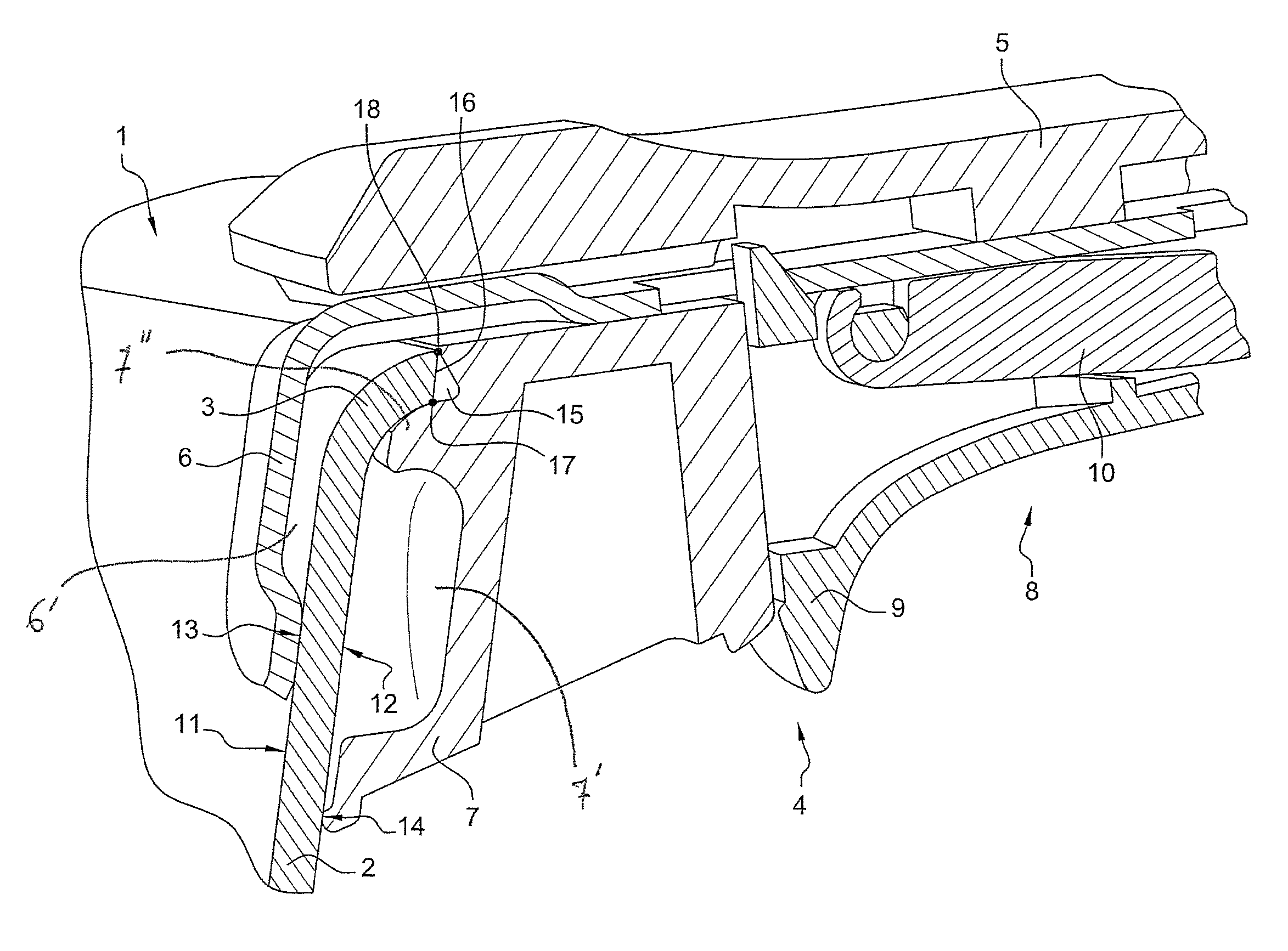
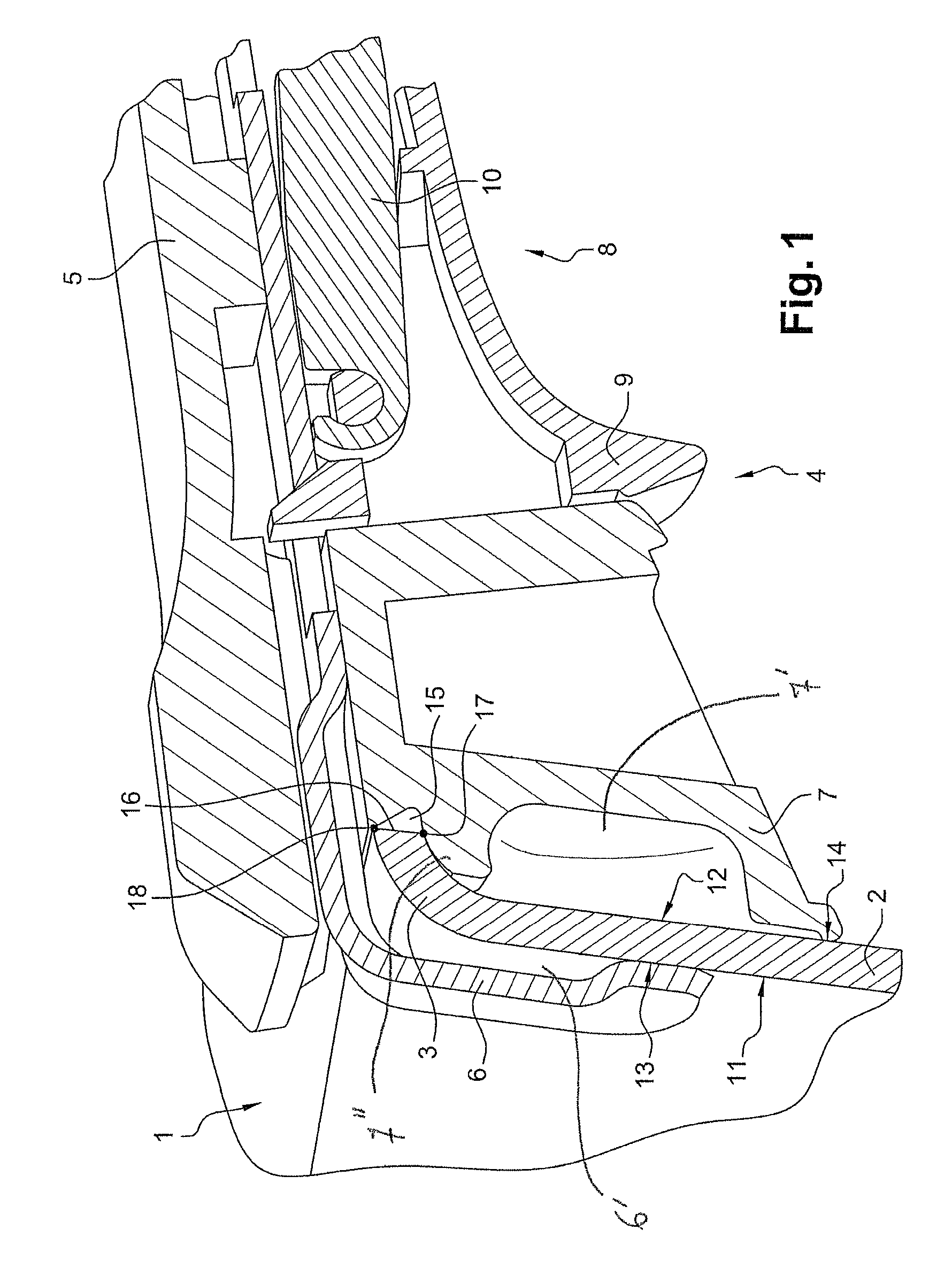
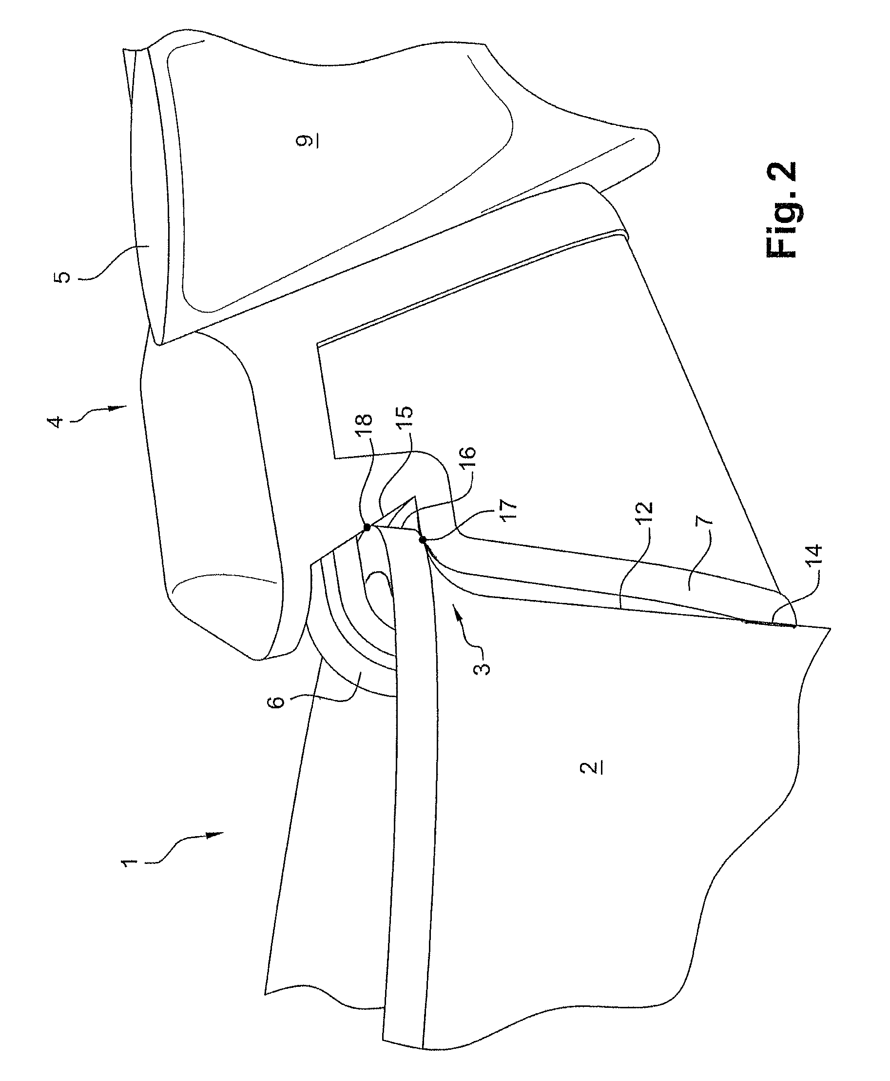
[0015]Conventionally, a kitchen accessory 1 includes a horizontal base wall, a lateral wall 2 standing up from the base wall, and a curved portion 3 that is curved outwardly, which extends the lateral wall 2, which defines the upper opening of the kitchen accessory 1 and which forms the upper end of the latter.

[0016]In parallel, a removable handle 4 includes a grip body 5 that acts as a stick and that enables a user to grasp it, and two jaws 6, 7 that are mobile one with respect to the other between an open position enabling the lateral wall 2 to be arranged between the jaws 6, 7 and a closed position in which the jaws 6, 7 clamp the lateral wall 2. The removable handle 4 also includes actuation means 8 that can be moved by the user and drive the relative movement of the two jaws 6, 7. In this case, these means 8 are mobile between an opening position in which the jaws 6, 7 are in their open position, and a closing position in which the jaws 6, 7 are in their closed position. More s...


PUM


Abstract

Provided is a removable handle for a kitchen object, having a lateral wall extending upwardly by a part that is curved back towards the outside, the handle comprising an inner jaw and an outer jaw to be respectively brought against the inner and outer surfaces of the lateral wall, the two jaws being mobile in relation to each other between an open position and a closed position wherein they pinch the lateral wall. The outer jaw comprises a groove that can receive the free end of the curved part of the lateral wall in abutment when the jaws are in the closed position thereof.

Description

BACKGROUND OF THE INVENTION[0001]1. Field of the Invention[0002]This invention relates to a removable handle for a kitchen accessory, a kitchen accessory such as a pan, having a lateral wall that extends upwardly by an outwardly curved portion.[0003]2. Prior Art[0004]Numerous handles for kitchen accessories are known, of the type including an internal jaw and an external jaw suitable for abutting the internal and external surfaces, respectively, of the lateral wall of the kitchen accessory, in which the two jaws are mobile one with respect to the other between an open position and a closed position in which they clamp the lateral wall.[0005]Such a handle also includes jaw actuation means, which means can be varied and, in general, their design is associated with an improvement in ergonomics.[0006]In addition, some handles have technical features enabling specific technical problems to be solved, for example: preventing from a sudden and unexpected opening of the jaws in spite of the...

Claims


Application Information

Patent Timeline
IPC IPC(8): A47J36/00A47J45/07
CPCA47J45/07A47J45/071A47J45/00
Inventor MONTGELARD, MICHEL
Owner SEB SA
Why Eureka
Try Eureka