Throwaway rotary cutting tool

a rotary cutting and rotary cutting technology, applied in the direction of shaping cutters, manufacturing tools, wood boring tools, etc., can solve the problems of vibration and chatter noise during machining, weaker radial portions of the tool, and heavy load on the tool, so as to efficiently and stably machine the blade root of the turbine blad

Inactive Publication Date: 2014-08-19
OSG
View PDF30 Cites 14 Cited by
  • Summary
  • Abstract
  • Description
  • Claims
  • Application Information

AI Technical Summary

Benefits of technology

[0005]The present disclosure is made to solve the problems that are described above, and it is an object of the present disclosure to provide a throwaway rotary cutting tool that can machine a blade root of a turbine blade efficiently and stably.

Problems solved by technology

However, with the cutting tool that is described in the Patent Document 1, rough cutting of the complex blade root is done by a single tool, so a heavy load bears on the tool, and in particular, the portions of the tool that are narrower in the radial direction are weaker than other portions.
Therefore, vibration and chatter noise may occur during the machining.
Moreover, in a case where the machining is continued in this sort of unstable state, the tool may break, particularly in the narrower portions, so the machining must be done while limiting the cutting feed of the tool, accordingly efficient machining may not be done.
Furthermore, the shapes of the cutting tips must be matched to the contour of the blade root, so ordinary rectangular cutting tips that are commercially available may not be used.
Therefore, the cost of manufacturing the cutting tips may be expensive.

Method used


Image

  • Throwaway rotary cutting tool
  • Throwaway rotary cutting tool
  • Throwaway rotary cutting tool

Examples


Embodiment Construction

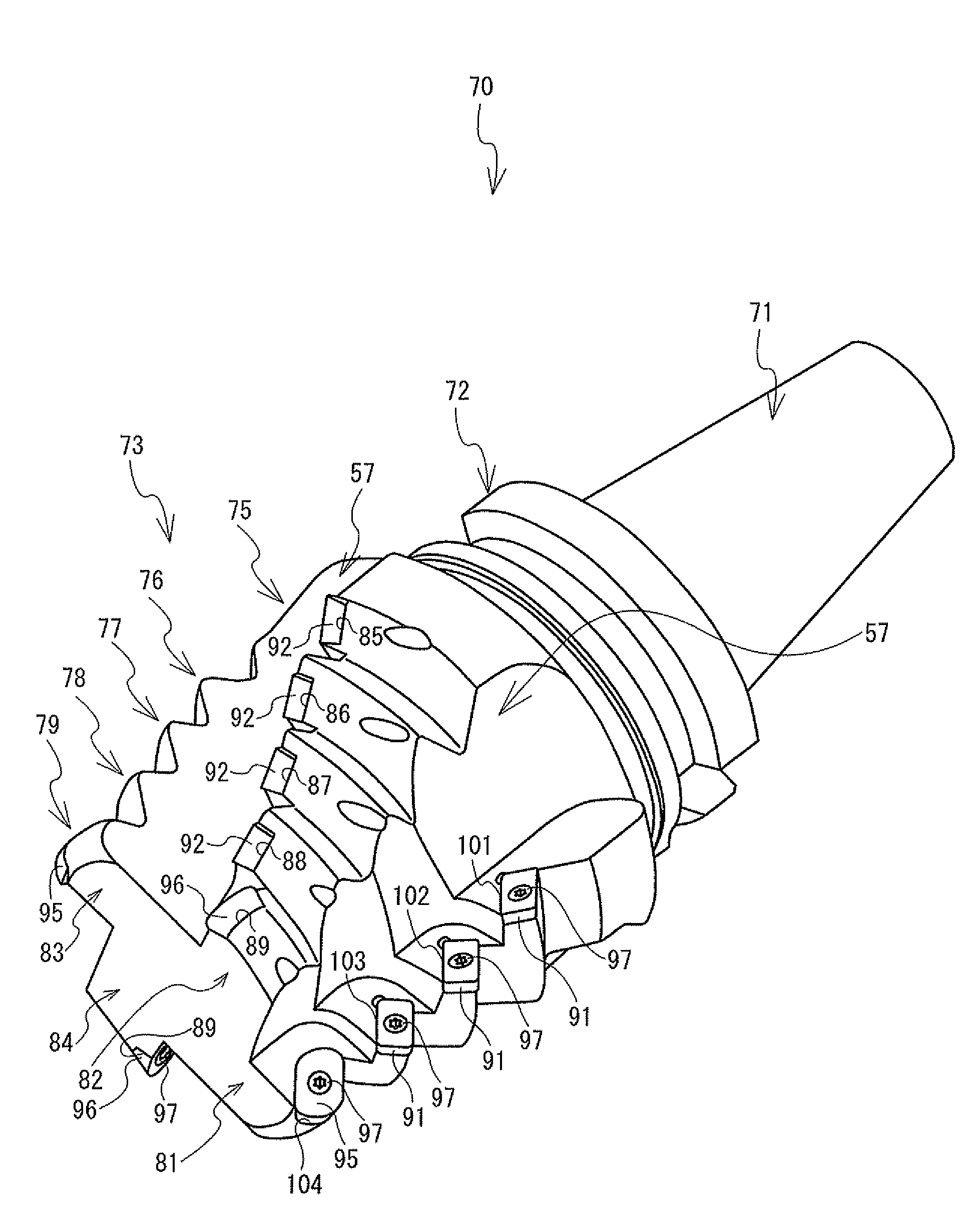
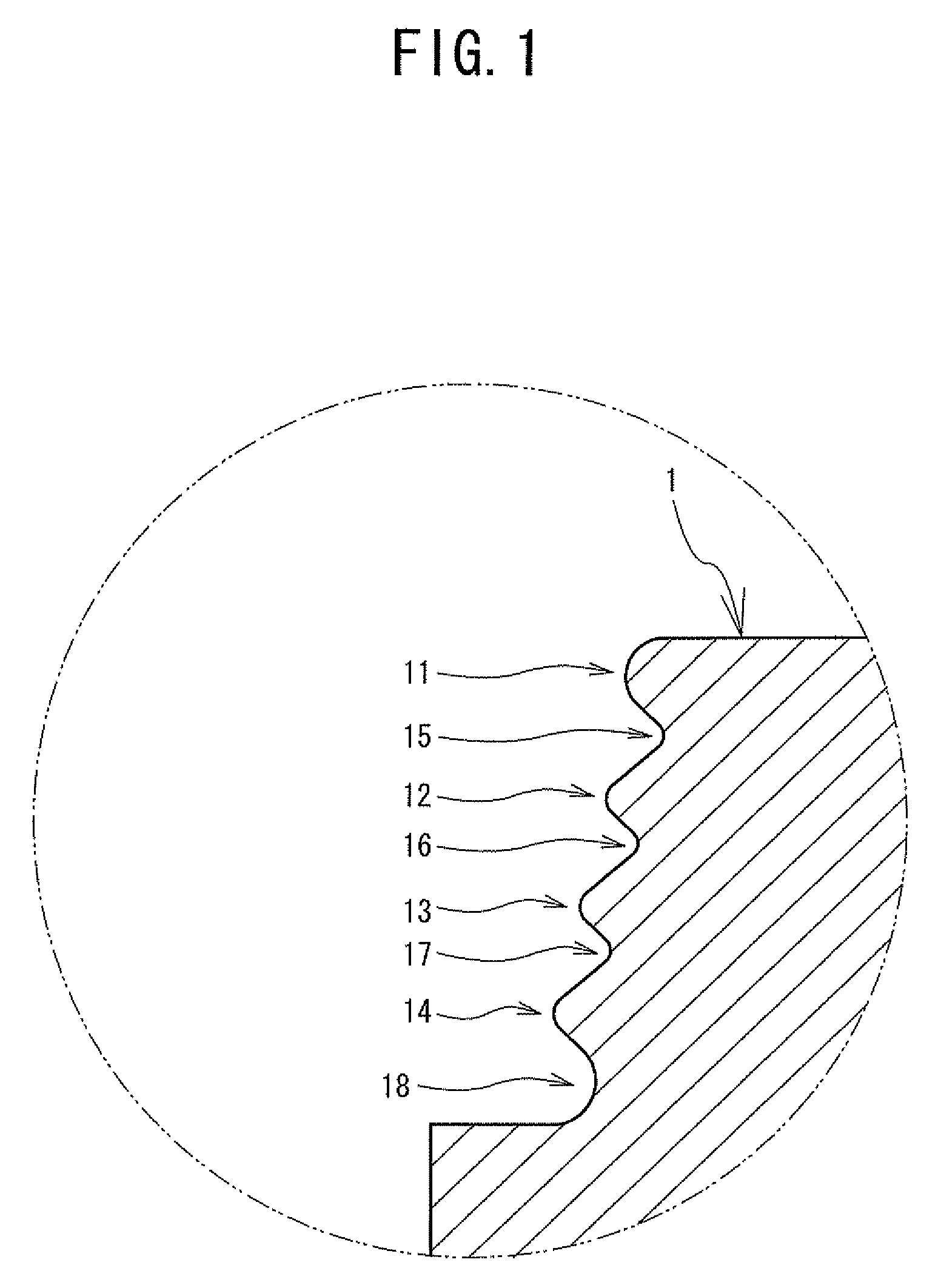
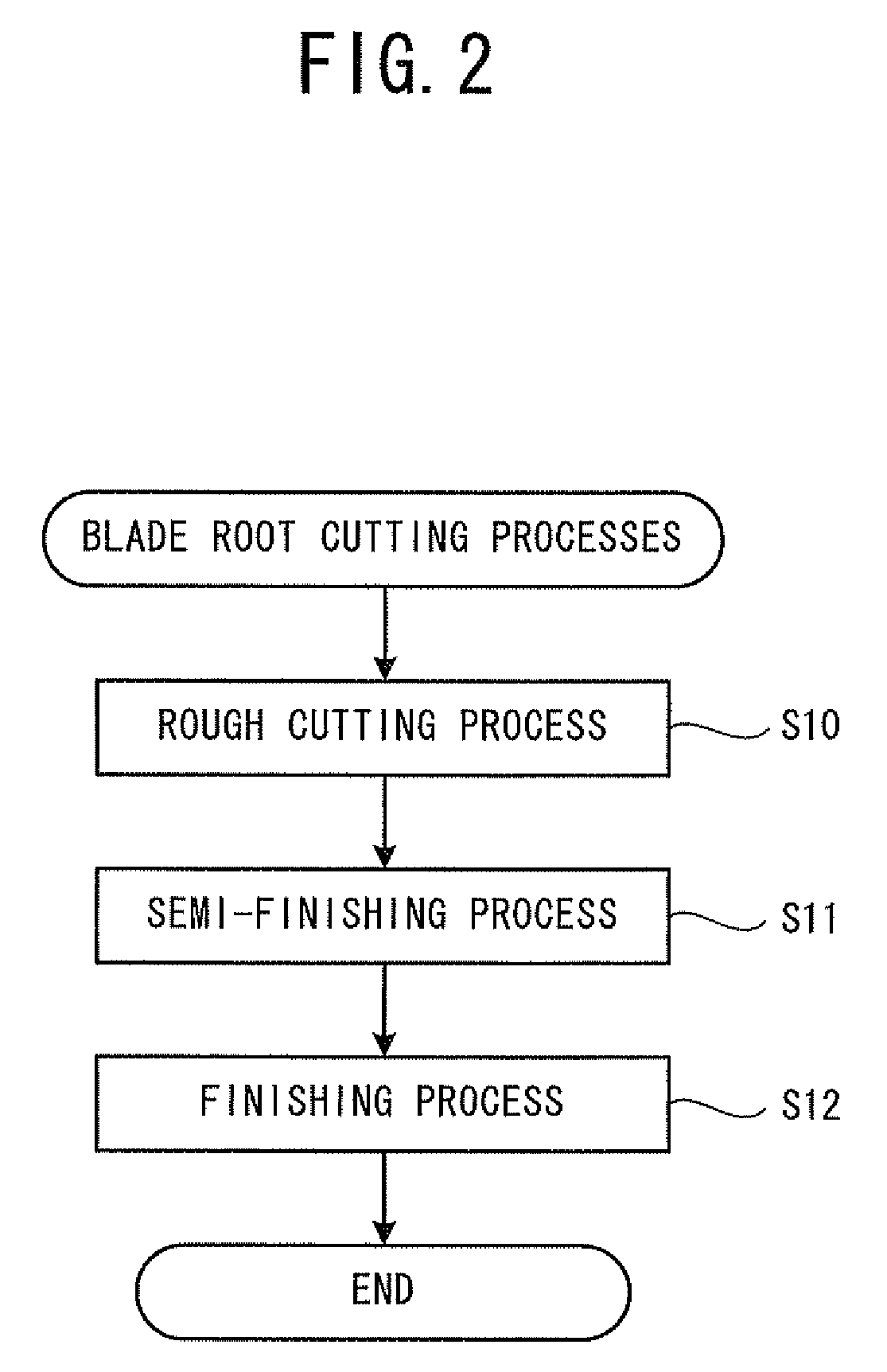
[0025]Hereinafter, a semi-finishing cutter 70 that is an embodiment of the present disclosure will be explained with reference to the drawings. A blade root 1 that is shown in FIG. 1 is a base portion for mounting a turbine blade (not shown in the drawings) into a slot that is formed in the outer circumference of a rotor (not shown in the drawings) that is used in a generator. The semi-finishing cutter 70 that is shown in FIG. 12 is a throwaway type of rotary cutting tool that is used in a semi-finishing process (refer to FIG. 2, S11) that is performed as the second of a series processes for cutting the blade root 1.

[0026]First, the shape of the blade root 1 will be explained. As shown in FIG. 1, the blade root 1 that is the base portion of the turbine blade is bilaterally symmetrical with respect to its own longitudinal direction, and is formed such that the blade root 1 gradually becomes narrower towards a tip end, in an upside-down Christmas tree shape in which the width of the r...


PUM

PropertyMeasurementUnit
diameteraaaaaaaaaa
widthaaaaaaaaaa
diameteraaaaaaaaaa

Abstract

In a semi-finishing cutter, rectangular tips and square tips are disposed in a staggered pattern in an axial direction in second to fourth step portions, so a single cutting edge is formed by a pair of one of the rectangular tips and one of the square tips. It is therefore possible to effectively reduce a frequency of contact with a blade root. A cutting speed of the semi-finishing cutter may be increased and a cutting feed may be made faster, so work in a semi-finishing process may be performed efficiently. The rectangular tips and the square tips have simple shapes, so known commercially available throwaway tips may be used. Accordingly, it is possible to provide the semi-finishing cutter in an easy-to-use form without increasing the cost.

Description

TECHNICAL FIELD[0001]The present disclosure relates to a throwaway rotary cutting tool, and more specifically relates to a throwaway rotary cutting tool for cutting a blade root of a turbine blade that is to be mounted on the outer circumference of a rotor.BACKGROUND ART[0002]In a case where a known turbine blade for a generator is manufactured, the contour of a blade root of the turbine blade must match the shape of a Christmas tree-shaped slot that is formed in the outer circumference of a rotor so that the blade root may be mounted into the slot. The blade root is generally bilaterally symmetrical with respect to its own longitudinal direction, is machined such that the blade root gradually becomes narrower towards its tip, in an upside-down Christmas tree shape in which the width of the root increases and decreases, and is formed such that narrow portions where the root width becomes less alternate with wide portions where the root width becomes greater.[0003]In order to machine...

Claims


Application Information

Patent Timeline
Patent Type & Authority Patents(United States)
IPC IPC(8): B23C5/10B23C3/30B23C5/20
CPCB23C5/109B23C3/30B23C2210/285B23C2210/086B23C2220/366B23C2220/60Y10T408/905Y10T407/1924Y10T407/1962Y10T407/195Y10T407/196
Inventor ITOH, TASUKUHAMATAKE, YASUOWATANABE, KATSUTOSHI
Owner OSG
Why Eureka
Try Eureka