Thin backlight system and liquid crystal display device using the same

a backlight system and liquid crystal display technology, applied in the direction of illuminated signs, display means, instruments, etc., can solve the problems of color breakage, low light use efficiency of liquid crystal display devices including color filters, and loss of approximately two-thirds of lights, etc., to suppress chromatic aberration, increase light use efficiency, and reduce color loss

Inactive Publication Date: 2014-08-19
SHARP KK +1
View PDF13 Cites 0 Cited by
  • Summary
  • Abstract
  • Description
  • Claims
  • Application Information

AI Technical Summary

Benefits of technology

[0048]According to the present invention, a thin backlight system can converge lights having different dominant wavelengths, which lights are emitted from a light emitting section, on a respective plurality of corresponding light transmitting parts. That is, it is possible to spatially separate the lights having the different dominant wavelengths. Further, in a case where the backlight system is used as a surface light source of a liquid crystal display device, it is possible to converge the lights having different dominant wavelengths, which lights are emitted from the light emitting section and spatially separated from each other, on corresponding portions of a liquid crystal layer. This makes it possible to achieve both (i) an increase in a use efficiency of the lights from the light emitting section and (ii) a full-color display. Further, since the lights having the different dominant wavelengths, which lights are emitted from the light emitting section, are deflected by being partially or totally reflected so as to travel in substantially parallel to a normal to an imaging optical system, a large chromatic aberration does not occur.
[0049]That is, a thin backlight system in accordance with the present invention is capable of suppressing a chromatic aberration in spite of its small thickness.

Problems solved by technology

However, since each of the R, G, and B color filters transmits a light of its corresponding waveband and absorbs a light of other waveband, the liquid crystal display device including the color filters suffers from a loss of approximately two-thirds of lights.
That is, the liquid crystal display device including the color filters has a low use efficiency of lights.
Note here that, although there has been a field sequential color method which is one of full-color display methods using no color filters, the field sequential color method has a problem in which color breakup occurs.
Note, however, that Patent Literature 1 does not exclude provision of color filters for preventing colors from being accidentally mixed due to light leakage resulting from an undesirable result of the color separation.

Method used


Image

  • Thin backlight system and liquid crystal display device using the same
  • Thin backlight system and liquid crystal display device using the same
  • Thin backlight system and liquid crystal display device using the same

Examples


examples

[0152]The following description discusses, with examples and comparative examples, results of concrete studies into effects of the present invention. Note, however, that the present invention is not limited to the examples described as below.

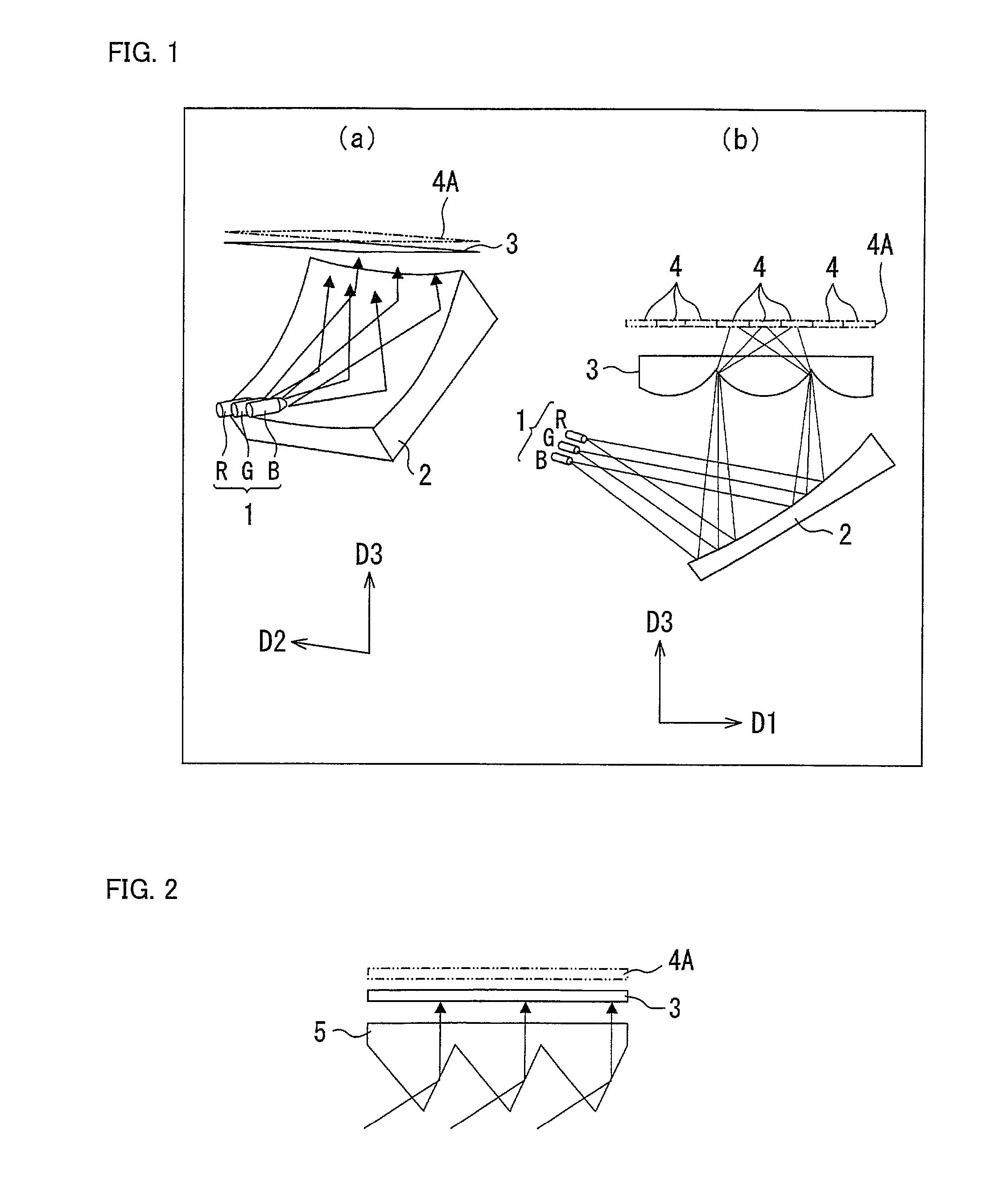
[0153]A thin backlight system configured as illustrated in FIG. 2, which backlight system serves as an example of the present invention, was experimentally produced. The thin backlight system includes point light sources 1 constituted by (i) an LED that emits a light having a dominant wavelength of R, (ii) an LED that emits a light having a dominant wavelength of G, and (iii) an LED that emits a light having a dominant wavelength of B. The point light sources 1 were lit, and spatial luminance distribution of lights emitted from top surfaces of microlenses was measured with use of a luminance and chromaticity uniformity measuring device (manufactured by TOPCON TECHNOHOUSE CORPORATION, UA-1000). The LED of R, G, and B of the point light sources 1 ...


PUM

PropertyMeasurementUnit
angleaaaaaaaaaa
angleaaaaaaaaaa
anglesaaaaaaaaaa

Abstract

A thin backlight system includes: a light emitting section emitting lights that have different dominant wavelengths; and a plurality of light transmitting portions, the thin backlight system deflecting the lights and then converging the lights on the plurality of light transmitting portions. The thin backlight system further includes: an imaging optical system provided to face surfaces, of the plurality of light transmitting portions, on which the lights are converged. The imaging optical system including a plurality of identical lenses arranged in a vertical and / or a horizontal direction at a pitch determined by multiplying a pitch at which the plurality of light transmitting portions are arranged in a vertical and / or a horizontal direction by the number of types of the different dominant wavelengths and being configured to converge the lights from the light emitting section on light transmitting portions to which the different dominant wavelengths of the lights correspond.

Description

TECHNICAL FIELD[0001]The present invention relates to a thin backlight system and a liquid crystal display device including the thin backlight system. Specifically, the present invention relates to (i) a thin backlight system for converging lights having different colors on back surfaces of respective corresponding picture elements, which correspond to the different colors of the lights and are included in each pixel of a transmissive liquid crystal display element, and (ii) a liquid crystal display device including the thin backlight system and the liquid crystal display element so as to carry out a full-color display.BACKGROUND ART[0002]Conventionally, a full-color liquid crystal display device has been realizing a full-color display by (i) dividing each pixel of a transmissive liquid crystal display element into three picture elements, (ii) attaching red (R), green (G), and blue (B) color filters to the respective three picture elements, (iii) emitting, from a backlight, white li...

Claims


Application Information

Patent Timeline
Patent Type & Authority Patents(United States)
IPC IPC(8): G02F1/1335
CPCG02B5/045G02B19/0028G02B19/0047G02B19/0066G02F1/133605G02F1/133615G02F2001/133607G02F2001/133622G02F1/133622G02F1/133607
Inventor UCHIDA, TATSUOSUZUKI, YOSHITOKAWAKAMI, TOHRUSEKIYA, KAZUOISHINABE, TAKAHIROKATAGIRI, BAKUHASHIMOTO, YOSHIHIROISHIHARA, SHOICHIKOZAKI, SHUICHIISHII, YUTAKA
Owner SHARP KK
Why Eureka
Try Eureka